
It’s not unusual for me to get help requests through my e-mail. Sometimes it’s from working technicians; other times it’s from vehicle owners who can’t get their problems solved through professional repair shops. Not that I successfully solve each one because I depend solely upon the individual’s description of the problem and upon the information he or she supplies.
But I received one of my most challenging e-mail requests from a shop foreman of a Honda dealership. This service manager had read a column I’d written on PCM diagnostics for ImportCar and was asking my opinion about why three PCMs would consecutively fail on a 2002 Honda Civic equipped with an automatic transmission and with 137,000 miles on the odometer.
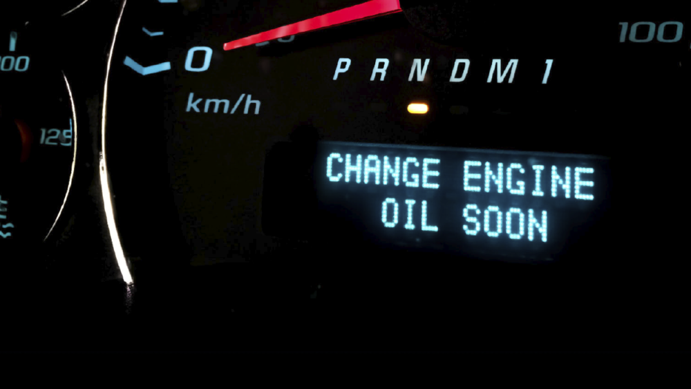
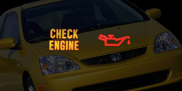
Needless to say, these failures were becoming very expensive for the Honda dealer, which was the port of last resort for the Honda’s owner. The first repair visit was for a no-start complaint with the check engine light (CEL) on and immobilizer key light flashing. The Honda scan tool wouldn’t communicate with the PCM. Following Honda service information concerning no communication, the technician replaced the PCM with a known-good unit and reprogrammed the immobilizer. The test PCM was replaced with new and the customer took the vehicle.
One week later, the vehicle was towed in with a loss of power, CEL on and a P1607 code indicating an internal PCM failure. After testing power and ground circuits, the technician replaced the new PCM with another as prescribed in Honda service information.
THE USUAL SUSPECTS
At this point, I suggested rounding up the usual suspects, one of which might be that the alternator was intermittently over-charging the battery. Of course, the technician’s problem was that a third PCM would need to be installed to get the engine and electrical system operational. In general, a charging rate exceeding 17.0 volts will begin burning out light bulbs and ruining system electronics like radios and PCMs.
The best method for capturing intermittent excessive voltage or voltage spikes is to display the system charging voltage on a labscope. Another source for voltage spikes are failed diodes in the air conditioning compressor clutch and similar high-amperage circuits. Although modern PCMs are generally well-protected against voltage spiking caused by alternators, A/C clutches, starter relays, and even battery chargers and jumper cables, anything is a possibility in extreme cases like this.
After replacing the PCM, the technician found that the charging voltage was above 15.5 volts. He replaced the alternator and cleaned all engine and chassis grounds. The charging voltage then dropped to a steady 14.5 volts, with a 0.03 voltage drop as measured between the alternator housing and the battery B- post. After about 60 minutes at idle speed, the engine suddenly raced to 3,500 rpm and then stalled and wouldn’t re-start. The immobilizer light was flashing and the CEL was illuminated.
The Civic also wouldn’t communicate with the Honda scan tool. The B+ voltage at the PCM measured 10.6 volts and the voltage drop on the ground side measured 0.03 volts when cranking. The PCM wiring was then tested with a breakout box to make sure that no internal wiring harness shorts were present and to ensure that all power circuits were operating at correct voltages. No aftermarket accessories or wiring damage was observed.
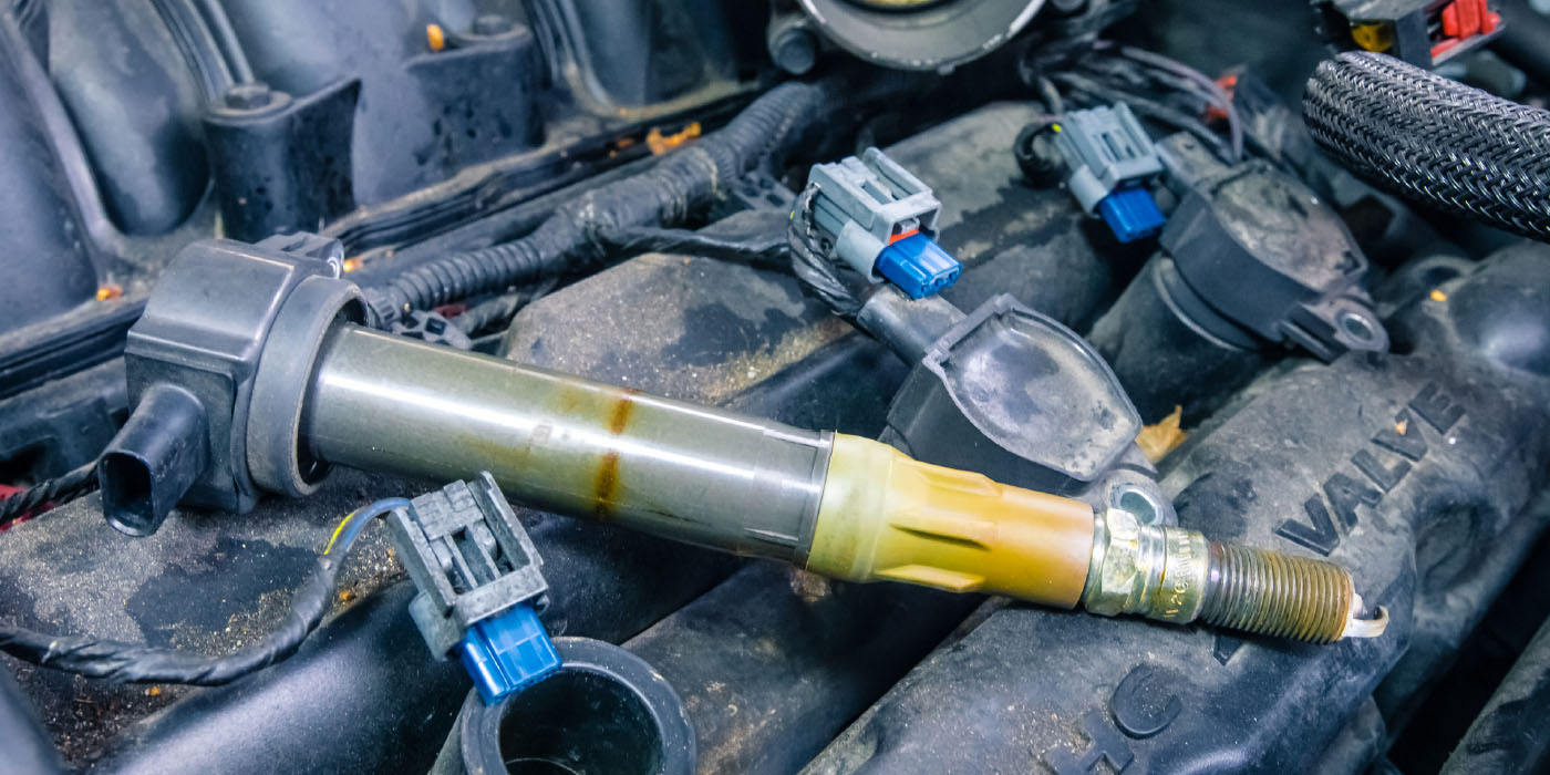
Returning to the voltage spiking issue, the technician replaced all ignition coils, fuel injectors, sensors, main ignition relays, battery and PCM with known-good parts. The engine then ran for one hour and 45 minutes before it died, with the CEL illuminated and immobilizer light flashing. A scan tool snapshot taken with the engine running didn’t show any irrational engine data. Amperage draw checks were made on all actuators to ensure that none were drawing excessive amperage.
The failed PCMs transferred the symptom of the flashing immobilizer light when installed in another vehicle, which lead me and the technician to believe that the fault was with the PCM. None of the failed PCMs showed any internal evidence of burns or heat damage. The PCMs were then sent to a repair service for testing. The repair service reported that the processors in all three PCMs were ruined.
At this point, I’d like to interject that I’m not a Honda specialist, not because I haven’t serviced my share of Hondas, but because the Hondas that I’ve serviced were very reliable vehicles and none, in my experience, ever had major electronic issues. The most common electronics problems that I encountered were ignition module failures on the early models and a few false P0420 catalytic converter trouble codes on later models that needed reprogramming to correct.
BUS COMMUNICATIONS
With that said, we’re now in an era of body control electronics in which various modules, including the PCM, share information through a bus communications system. During the early 1990s, some high-end European vehicles began using high-speed communications systems to not only share information, but to prioritize and control communications among the various modules.
The result of these developments is the now-familiar Controller Authority Network (CAN) communication systems. Due to the need for high-speed bus communications to operate and prioritize various safety features like vehicle stability and many other modern-day accident avoidance systems, CAN was mandated by the federal government as standard equipment in 2008.
With that background in mind, it didn’t take me long to understand that – CAN system or not – it was apparent why the shop foreman and technician were both frustrated and puzzled by the Honda Civic’s insatiable appetite for PCMs.
AT A LOSS
At this point, Honda’s technical support couldn’t offer a solution. After looking through my own aftermarket information for a 2002 Civic, I found that I was also at a major disadvantage when dealing with Honda body control and vehicle immobilizer issues. Part of that problem was that the automotive manufacturers in that day refused to publish technical and repair information about their vehicle security systems.
So I had no idea of what the operating strategy might be on the immobilizer system, nor did I know why the failing PCMs would cause the immobilizer light to flash. Adopting one of my earlier suggestions, the technician disabled the alternator voltage regulator to eliminate electrical interference from the charging system. He also attached a labscope to the PCM B+ terminal to detect voltage spikes.
On a roll of the diagnostic dice, the technician elected to install a known-good multiplex control unit (MICU) and immobilizer control unit, along with a known-good PCM. Fourteen hours of running time revealed no voltage spike at the PCM B+ pin. Eighteen hours of driving time was put on the Civic with no failures observed.
The shop manager and technician speculated that, although neither had seen such a failure, the MICU or immobilizer module were in some fashion corrupting the processor in the three failed PCMs via the communications bus. In theory, at least, it would be possible that this could happen and, in practice, it turned out that replacing two suspect parts solved the problem.
DIAGNOSTIC SUMMARY
I tried to duplicate the narrative of the above case study as closely as I could. Obviously, I likely haven’t covered all the nuances of the problem simply because communicating by e-mail has its limitations. We also need to remember that this case study took place in a dealership which no doubt had some trade-in and scrap vehicles from which to salvage substitute parts. Certainly not due to lack of expertise at the shop level, the 2002 Honda Civic was repaired at a considerable investment of time and money by the dealer. But, if nothing else, this case study illustrates some of the many holes in diagnostic theory.
In this case study, the hole in our diagnostic theory is the fact that the MICU and immobilizer modules were, in some fashion, rendering the processor in the Civic’s PCM inoperable. Despite the fact that pinpoint testing usually reveals the root cause of these types of failures, we can easily get into unknown territory, especially with the immobilizer systems on early 2000 and newer imports, for which only a minimal amount of service information was released.

GETTING STARTED ON BUS COMMUNICATIONS
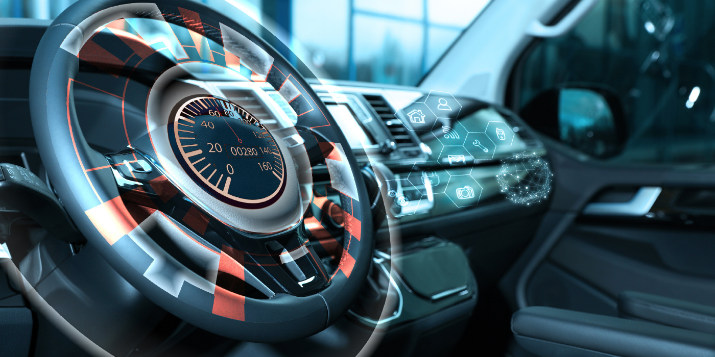
To better prepare for CAN bus communications diagnostics, it’s important to remember they’re very application-specific and are becoming even more complex with the addition of telematics and “infotainment” systems, all of which makes them far more difficult to master and to diagnose.
As a first step, you can begin to understand how modules communicate with each other by the simple process of polling all vehicle modules for both communications and trouble codes before diagnosing any no-start complaint. If you have a module that’s not communicating, you should be able to retrieve a U1000-series diagnostic trouble code (DTC).
The U1000-series DTCs will contain numbers that identify the offending module or that information will be contained in the DTC description and enabling criteria. Remember, too, that with some configurations of on-board modules, a single bad module can pull down the whole bus communications system. In this case, the offending module must be disconnected before bus communications can be restored.
The next step is to invest in a Diagnostic Link Connector (DLC) break-out box (BOB). (See above photo.) BOBs essentially eliminate the need for determining which DLC pin is carrying which bus communications signals. Generally priced from $200 to $400, BOBs are a relatively inexpensive method for determining the presence of bus communications signals.
In addition to LEDs indicating that a particular bus system is communicating, the BOB should also have banana-plug ports that allow a technician to connect a multimeter or labscope directly into the bus communications system to evaluate the presence and quality of bus signals. Last, it’s important to get up-to-date training on bus communications diagnosis.