Taking the car apart with a screwdriver in one hand and a flashlight in the other isn’t always the best diagnostic technique for diagnosing routine problems like parasitic battery drains, worn ignition switches, bad grounds, bad ignition modules and bad relays. In contrast, keeping the diagnostic process simple by using a professional multimeter to diagnose circuit defects in modern electrical systems through the under-hood and interior fuse boxes is like putting money in the bank. In short, the multimeter is the first tool — and perhaps the last tool — I’ll reach for in my diagnostic tool box when diagnosing electrical system problems. I hope the following text will explain why.
REINVENTING OHM’S LAW: Multimeters and Ohm’s Law are inseparable diagnostic partners. To keep Ohm’s Law simple, I use the formula volts = amps x ohms, which works with direct current (DC) flowing through a solid wire. To illustrate, a circuit with 6 ohms resistance flows 2 amps. According to the above formula, 6 ohms x 2 amps = 12 volts. In other words, 12 volts of electrical potential or “pressure” is required to make 2 amps flow through a 6-ohm resistance. If we reduce the 2-amp current flow to one amp, an electrical potential of only 6 volts is required to make one amp flow through a 6-ohm resistance. If voltage is doubled on the 2-amp, 6-ohm circuit, the current flow increases to 4 amps. So, you get the idea: volts, amps, and ohms are interdependent, which is why measuring volts, amps, and ohms with a digital multimeter is making a comeback in our diagnostic world.
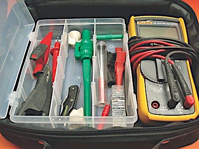
METER CAPABILITIES: Most professional multimeters cost around $100 to $150 for a base model and around $400-$500 for a meter with most of the diagnostic bells and whistles. If we look closely at their features, we’ll immediately discover that multimeters can read both alternating current (AC) and direct current (DC). Remember that you need to buy multimeters that meet specific safety requirements when testing high-voltage hybrid or electric vehicle systems. Some manufacturers make multimeters with many task-specific features, like measuring engine rpm. So, when you choose a meter, make sure it will meet your specific task requirements.
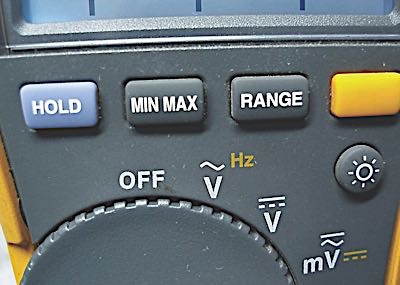
switches the meter to the functions printed
in yellow above “volts” and “millivolts.”
The round button at the right controls the
meter’s back-lighting.
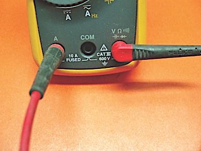
Professional multimeters have a minimum/maximum recording system indicating min/max amperage, voltage and resistance. Most professional meters can read positive and negative duty cycles, which is important when diagnosing on-time and off-time DC circuits. Multimeters can also test diodes, capacitors and circuit continuity. Most important, a multimeter can provide direct measurements of up to 10 amps of current flow through any DC circuit. The meter’s low-amp and 10-amp circuits are internally fused. These fuses can easily blow when testing a B+ circuit with the meter selector switch in the amp test mode. For most meters, the continuity of these fuses can be tested by selecting “ohms” and plugging the positive test lead into the 10-amp and low-amp ports. Higher amperages are more safely measured by using inductive amperage probes.
Both of my higher-end multimeters incorporate a “relative” button that conveniently “zeros” or subtracts the resistance in the test leads from the total reading when testing circuits or when using zero-sensitive accessories like inductive current probes or pressure transducers. If the meter doesn’t have the “relative” feature, test lead resistance is determined by connecting the positive and negative test leads to determine their resistance and then subtracting that number from the total resistance of the component being tested. Zero-sensitive accessories have their own zeroing devices for use with meters that don’t have the ”relative” feature.
Last, the “True RMS” (true root mean square) feature of many multimeters refers to the ability of the meter to accurately measure the voltage of an asymmetrical sine waveform like that found on a two-wire magnetic reluctor-type sensor. So, while that task is more ably done by a lab scope, it can also be done with a True RMS multimeter. Since multimeters take a beating in the field, look for resistance to impacts, resistance to water and automotive fluids, and the availability of service and replacement parts. Back-lit displays and voltage bar graphs are also essential for working under dashes and measuring variable signals. Also, some multimeters carry a lifetime warranty, which makes them well worth their extra cost.
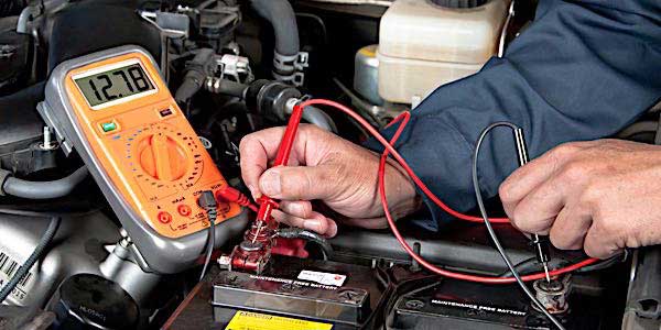
BATTERY QUICK TESTS: Since the battery is the heart of the electrical system, a multimeter can be used to quickly estimate the battery’s state of charge (SOC) and state of health (SOH). This is accomplished by measuring a battery’s open-circuit voltage (OCV). Any battery with an OCV under 12.4 volts won’t produce enough amperage to support extended ignition-on, engine-off electrical testing. In that regard, never make the mistake of using a battery charger to boost a discharged battery for electrical system testing because the system voltage will fluctuate in response to the charging mode and circuit breaker activity built into the battery charger.
A fully charged flooded-cell battery will test 12.6 OCV after the surface charge is removed by turning on the exterior lights for a few minutes. If the battery voltage is pulled below 12.6 volts while removing surface charge, a good battery should quickly recover to 12.6 volts. If the battery’s OCV voltage won’t recover, the battery’s SOH is questionable. Some absorbed glass mat (AGM) batteries might show 12.7 volts or slightly more with the surface charge removed. Batteries testing in the 10.0-volt range are either severely discharged or have a bad cell.
MEASURING PARASITIC DRAIN: Never try to measure parasitic drain by disconnecting the starter battery because several hours might elapse before all the on-board modules will time out or go to sleep. That said, parasitic battery drain is tough to measure on batteries with multiple B+ power and B- ground leads. Parasitic drain is also difficult to measure since an inductive amp probe measures the magnetic field surrounding an amperage-carrying wire. The accuracy of that measurement is influenced by competing magnetic fields from surrounding wiring and accessories. Keeping in mind that procedures may differ between meters, here’s the technique I use with my Fluke 115 to measure parasitic drain in these tough situations: Remove the ignition key or fob and leave it on the work bench to prevent accidentally locking it in the vehicle. With lights off, doors closed and front windows down: 1) Set the multimeter to “DC amps” and place the positive meter lead in the “com” port and the negative meter lead in the 10-amp port; 2) connect the B+ terminal of a small jumper battery to the starter battery’s B+ battery terminal; and 3) use the meter leads to ground the jumper battery to the engine, then disconnect the starter battery’s B- cable. The direct-reading amperage on the meter’s 10-amp scale will accurately represent the parasitic drain. Remember that the low-amp port can be used for a more precise measurement.
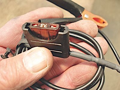
Normal parasitic drain with all modules timed out is well under 50 mA and usually well under 20 mA on newer vehicles. Remember that a small light bulb, an accessory or a module will draw around 200 millivolts (mV). Most modules will time out or go to sleep in about 20 minutes, while some might take several hours. Some aftermarket electronics might break all of the above rules by not going to sleep at all. That said, it’s a good idea to construct a 7.5-amp fused negative lead for your meter to protect the meter’s internal 10-amp fuse in case the ignition or exterior lighting is accidentally turned on.
TRACING PARASITIC DRAINS: Due to the ability of most meters to measure voltage to within one one-thousandth of a volt, a professional multimeter is indispensable for tracing parasitic drains. The simplest technique begins with connecting the meter’s negative lead to the battery B- terminal. With the front windows down, ignition key or fob removed, and all interior and exterior lighting off, use the positive lead to measure the voltage on each leg of each fuse in both the under-hood and instrument panel fuse boxes. You’ll notice that the negative legs of some fuses exhibit a slightly lower voltage than the positive. As per Ohm’s Law, this voltage drop represents a small parasitic drain passing through the fuse, which has a specific amount of resistance. I prefer using the vehicle owner’s manual to identify the fuse and function because it’s the most accurate source.
DETECTING WORN IGNITION SWITCHES: While not common, worn ignition switches can produce some intermittent low-voltage problems in the ignition, fuel pump and accessory circuits. To detect a worn ignition switch, connect the meter’s negative lead to battery ground. With the engine running, use the positive test lead to measure voltage at all ignition-on fuses. A high resistance through the ignition switch or ignition circuit is indicated if any fuses powered by the ignition switch show one-half volt less than battery voltage.
GROUND PROBLEM INDICATIONS: While we’re working in the under-hood fuse box, let’s use another technique for finding bad electrical system grounds. For years, we’ve known that electricity seeking a ground will follow the path of least resistance. With ignition on, ground the multimeter’s negative lead to B- and then use the positive lead to test voltage at the suspect fuses. If any of the fuses are displaying voltages “floating” well under B+ values, it’s because stray electricity from a loose or corroded ground circuit is trying to ground through one or more of those fuse circuits. Locating the faulty ground circuit is much easier if a ground distribution chart and a ground connector locator chart are used to identify all ground circuits.
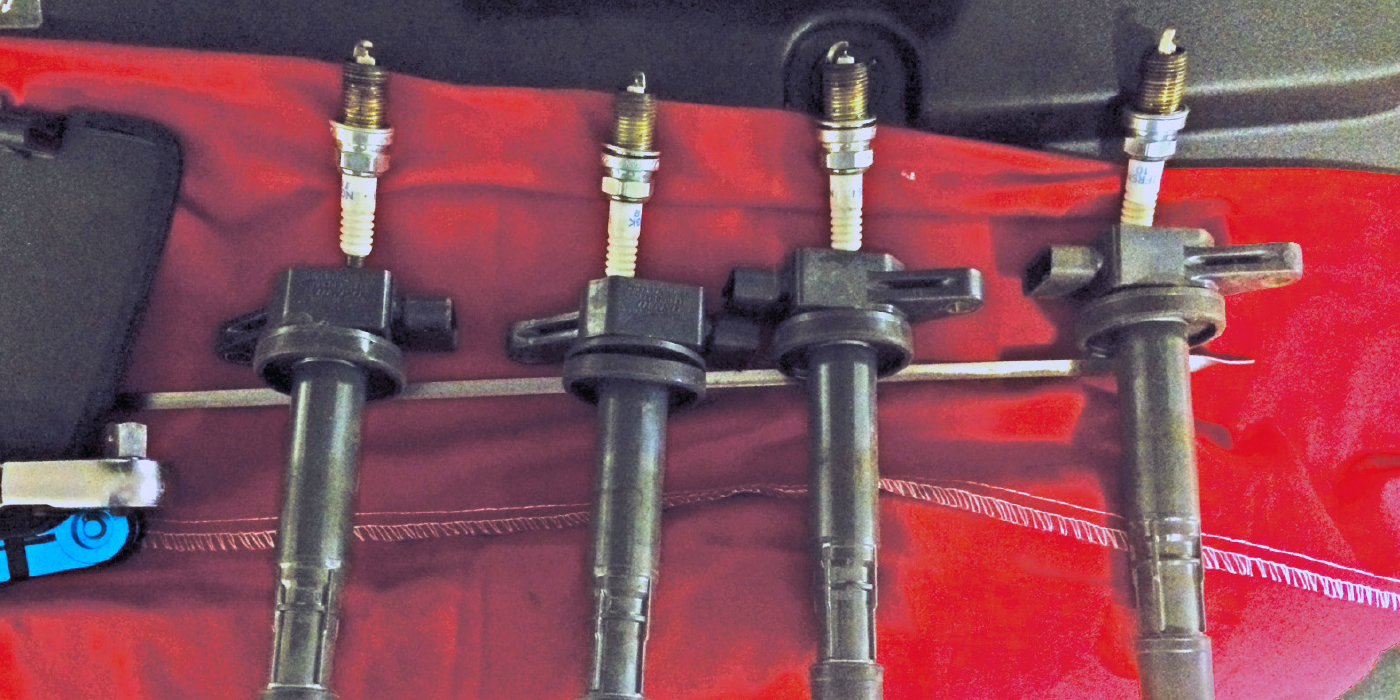
IGNITION SYSTEM TESTING: Going back to Ohm’s Law, voltage is reduced when electricity passes through resistance such as an ignition coil. To test an ignition module or PCM coil driver, compare the voltage at the coil’s B+ and B- connections while cranking the engine. While the coil B- value very much depends upon the coil driver duty cycle or “dwell angle,” coil B- should always measure much less than coil B+ if the ignition module or driver is switching the coil on/off as it should. If B+ and B- voltages are equal, the ignition module or coil driver isn’t switching the coil primary current.
RELAY TESTING: Relays work on the same principle as coil testing, with a driver in the PCM activating the relay by grounding the relay’s pin #85 or #86. High voltage at pins #85 or #86 indicates that the PCM driver isn’t activating the relay. Low primary voltage indicates that the PCM is activating the relay when commanded. With that said, we’re hopefully on to solving our next Diagnostic Dilemma with our humble and so very capable multimeter.
Article courtesy Underhood Service.