 To quote a familiar situation: “My customer’s car is now on its third alternator in six months and my jobber store refuses to warranty a fourth.” In other words, the parts supplier believes that an underlying problem is causing these alternators to fail and, therefore, won’t warranty more alternators. While we occasionally experience a sequence of failures caused by quality-control problems, the primary reason for most repeat failures is because the technician might have missed some critical steps during his initial diagnosis. To prevent expensive mistakes, it’s always best to “cover all the bases” during any charging system diagnosis.
INCREASED ELECTRICAL LOADS
Modern vehicle electrical systems require up to 20 amperes of electrical amperage to power the engine management, fuel delivery and accessory systems. When HVAC, engine cooling and exterior lighting is added to this base electrical load, the total load can rise to well past the 50-ampere mark. If the battery has a bad cell or is badly discharged due to excessive parasitic draw or accessory use, the alternator will be charging near its rated capacity, especially under severe driving conditions.
While modern alternators might be rated at 100 amperes or more, most compact designs aren’t designed to operate at full capacity for long periods of time without overheating. Due to excessively high charging rates, the replacement alternator might fail in short order.
BASIC OPERATING PRINCIPLES
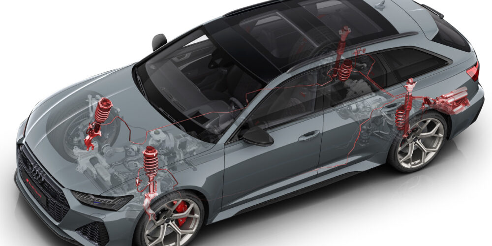
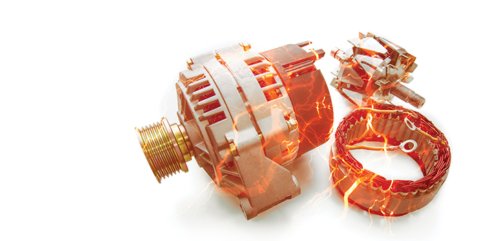
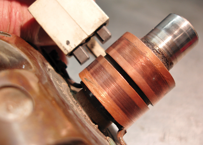
A conventional alternator contains four basic electrical parts: 1) rotor, 2) carbon brushes, 3) stator and 4) rectifier bridge. At the most basic level, an alternating current (AC) is produced when the copper wires wound through the alternator stator “cut” the rotating electromagnetic field created by the alternator rotor. The rotor “field” circuit is powered through a battery positive (B+) carbon brush riding on a copper slip ring mounted on the rotor shaft. A second carbon brush grounds the field circuit to the alternator case and ultimately to battery negative (B-).
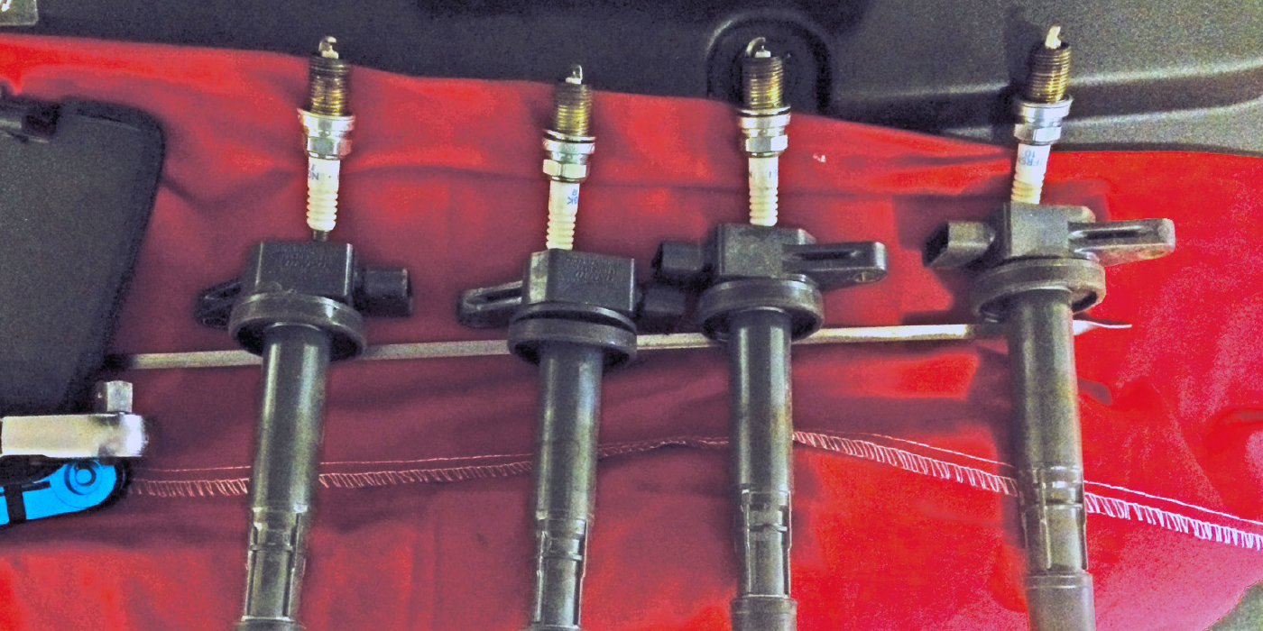
Alternator output amperage is controlled by increasing or decreasing the field amperage flowing through the carbon brushes, which, in turn, can increase or decrease the strength of the rotating magnetic field (see Photo 1).
An internally or externally mounted voltage regulator controls the field amperage. To accurately sense charging voltage, the voltage regulator must be connected to B+ and its base grounded to B- through the alternator case.
Depending upon the application, the voltage regulator can also be externally integrated into the powertrain control module (PCM). In more modern applications, the PCM controls an internal voltage regulator through a bus communications system or a reference voltage wire to modify the charging mode according to driving conditions (see Photo 2).
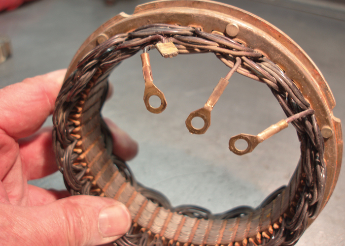
As illustrated above, the rotating magnetic field created by the voltage regulator is “cut” by three separate loops of copper wire wound through a stator assembly surrounding the field rotor. The stator produces AC, and the AC flowing through each stator loop is rectified to direct current (DC) by one positive and one negative diode.
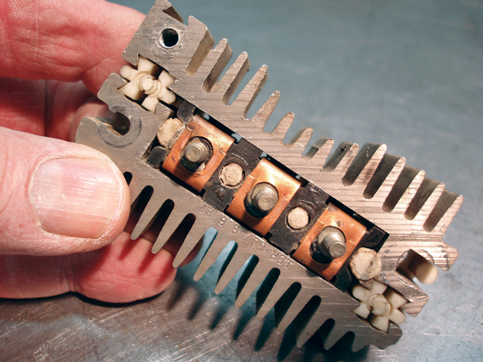
The six combined diodes are generally mounted on a heat sink assembly called a diode “bridge” that cools the diodes. These positive and negative diodes not only rectify AC current into DC current, they also prevent the stator from draining the battery when the engine is turned off (see Photo 3).
THE ROLE OF THE BATTERY
To prevent damaging the battery, lighting and on-board electronics, the alternator must limit voltage output to the battery. The battery plays a vital role in the voltage regulation process because it acts as a capacitor that dampens voltage spikes that occur in the electrical system. The battery also allows the alternator’s voltage regulator to more accurately sense battery voltage by acting as a resistor.
Keep in mind that the chemical activity of the battery electrolyte is directly related to the battery’s core temperature. The voltage regulator, therefore, is designed to limit charging voltage to about 15.2 volts in very cold weather and about 13.8 volts in very hot weather.
With these basics in mind, it’s obvious that a weak battery will reduce the service life of the alternator. To illustrate, the normal charging rate on a good battery includes a high-amperage, low-voltage charging mode (ex. 40 amps at 13.2 volts) called a “bulk” charging mode. Once the battery terminal voltage approaches 14.0 volts, the charging amperage decreases while the voltage increases (ex. 5 amps, 14.2 volts), which is called a “saturation” mode.
Modern computer-controlled charging systems might also produce a “float” charging mode of about 2 amps at 13.4 volts, which indicates that the battery is fully charged and that the alternator output is primarily supplying the vehicle’s operating systems. While these amperages and voltages are typical of what we see in the field, both values depend largely upon the age and condition of the battery.
If the battery is badly sulfated from disuse, it will quickly recover from a completely discharged state to a fully charged state. If the battery has a defective cell or is generally worn out, it will overload the alternator because full charging voltage will never be reached at the battery terminals.
Consequently, the first step in diagnosing any alternator charging rate problem is to test the battery for state-of-charge (SOC) and state-of-health (SOH). If the battery fails the SOC test, it should be recharged at a rate that won’t overheat the battery. Keep in mind that modern absorbed glass-mat (AGM) batteries require lower charging voltages and amperage rates to prevent overheating the battery. In any case, always follow the manufacturer’s recharging recommendations or use a “smart” battery charger that programs the charging rate to the battery type.
Lastly, batteries begin to gradually degrade after installation. In many cases, batteries are under-rated by as much as 25% to accommodate normal degradation for warranty purposes. To compensate for battery degradation, some recent vehicle models incorporated an adaptive strategy into their charging system that adjusts the alternator’s charging rate to the battery’s SOH. When the battery is replaced with new, the charging system requires a scan tool to “re-learn” the SOH of the new battery.
MECHANICAL FAILURES
Many modern charging systems incorporate “decoupler” pulleys that function as one-way clutches, allowing the alternator to keep spinning as the engine decelerates. This decoupler effect reduces stress and vibration at the serpentine belt and on drive pulleys. In some cases, the decoupler can seize, which can produce a belt vibration. In other cases, the decoupler mechanism can completely fail, causing a no-charge condition.
While the EPDM rubber used in modern serpentine belts doesn’t normally crack and fray as it ages, it can wear to the point that the ribs on the steel drive pulleys will bottom out on the ribs of the belt. In many cases, this type of wear can cause slippage under high charging loads that is not accompanied by normal belt squeal. Most belt manufacturers supply simple rib wear gauges and some even supply smartphone apps that can instantly evaluate belt wear by using the phone’s camera feature.
ELECTRICAL SYSTEM DIAGNOSIS
Since charging systems on many modern vehicles are computer-controlled, I recommend connecting a scan tool for the initial diagnosis of any charging system failure. If the charging system is controlled by the PCM, a related trouble code likely will be stored. If you’re not familiar with the PCM-managed charging system on the vehicle, consult your service information for more detailed information.
Always confirm the indicated charging system voltage parameter data by loading the system by activating the accessories and exterior lighting, and then testing voltage at the battery. If the voltage varies, the charging system wiring or the PCM itself might be defective.
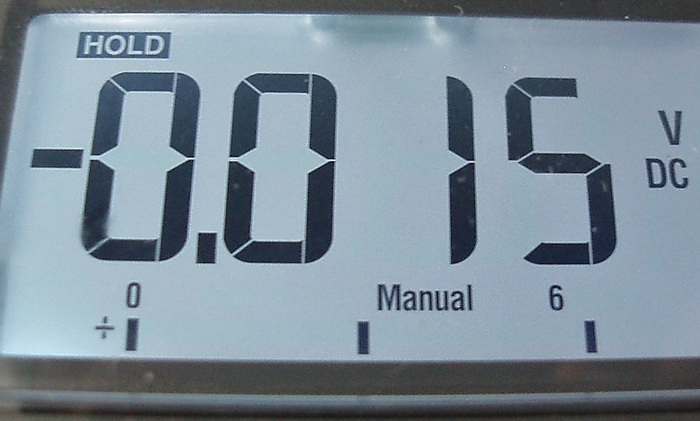
While your voltmeter is in hand, test for a ground system voltage drop by attaching it between battery B- and the alternator case or an engine ground. And, while you’re at it, perform the same test between B- and body/chassis ground. Similarly, check the voltage drop from battery B+ to alternator B+. A voltage drop less than 0.5 volts should be displayed for either test (see Photo 4).
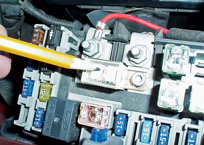
If the aforementioned B+ test indicates an open circuit, check the continuity of the charging system Maxi fuse located in the underhood fuse box. This fuse will be at least 100 amps capacity. Early alternators are connected to the battery with a fusible link as circuit protection. A simple test is to pull on the silicon insulation of the fusible link. If the insulation stretches, the internal low-melting temperature wire is burned in two (see Photo 5).
If the alternator isn’t charging, begin by testing the alternator voltage regulator fuse. In some applications, this fuse powers the voltage regulator, while, in others, it directly powers the alternator field circuit. To detect temperature-related failures, always let the alternator warm to operating temperature by running the engine with a full lighting and accessory load. If the voltage regulator fuse tests open-circuit, the voltage regulator, wiring or, in some cases, the field circuit in the alternator rotor can be shorted to ground. Repeated voltage regulator failure is generally caused by a short-to-ground in the alternator rotor itself.
Most alternator testing is done hot at 2,500 rpm engine speed. If the alternator won’t carry rated load under these conditions, suspect a slipping drive belt or bad alternator diode. If the alternator produces an intermittent charging condition, suspect bad wiring connections or, more commonly, worn or stuck carbon brushes.
With computer-controlled systems, make sure that the alternator is absolutely correct for the application. Even if the harness connector would plug into the alternator voltage regulator, the PCM’s software might not recognize or be able to communicate with the voltage regulator.
And don’t forget that each time routine maintenance is performed on a vehicle, the battery’s SOC and SOH should be tested to ensure that the battery is in good condition. A battery that’s in poor condition should be replaced not only to restore vehicle reliability, but also to reduce stress on the charging system.
Adapted from Gary Goms’ article in ImportCar.