Warped rotors are probably one of the most common complaints from drivers coming into any shop that does brakes. The less confident or sophisticated driver may complain that when he hits the brakes, “the pedal pulses,” “the vehicle chucks during a stop,” or “it shakes my teeth during braking.” Generally, a quick turn of the rotors and some fresh pads cures the pulsation complaint.
All of these descriptions fall into the general category of “brake roughness.” But, how sure are you that you have really fixed the problem, and how sure are you that it will stay fixed? Also, did machining the rotors and adding new pads provide a reliable, long-lasting repair?
Brake roughness is a complicated and often misinterpreted and misdiagnosed problem. At the root of brake roughness is a characteristic called Brake Torque Variation (BTV). This can be determined by measuring torque multiple times within one wheel revolution. The brake torque variation is the maximum torque measured within one revolution subtracting the minimum measured.
This test is done at a constant hydraulic pressure on a test bench or dynamometer in a laboratory. Ideally, the constant pressure would generate a constant torque through one revolution, thus making the BTV zero.
Tolerating BTV
Measuring BTV has little practical value in the field or at a shop. You can’t have roughness without having BTV, so measuring it only confirms what has already been observed. It is very valuable during vehicle design, as it provides insight into how much BTV a vehicle will tolerate.
You can tune the rest of the vehicle to absorb modest amounts of BTV. At levels above this sensitivity threshold, the vehicle will start to transmit the BTV back to the driver and generate a trip to the service center. This can take various paths:
- Pulsing of the brake pedal;
- Angular rotation in the steering wheel
(called nibble); - An up/down vibration in the steering wheel (called steering wheel shake); and
- Vibration in the seat track (called shake).
Seat track vibration can be felt at high frequencies and is generally described as a buzz or vibration. At low frequencies, it can be described as vehicle hitching or chucking. These behaviors are generally most noticeable at the end of the stop during light braking. The rate of “chucking” is usually close to one “chuck” per wheel revolution.
Asking the driver to distinguish between these events can be very critical in making sure you are fixing the right source of the problem. The roughness will generally be transient or only occur at specific speed ranges — light braking from 70 mph to 55 mph, for example. This results from the vibration pattern matching up with the frequency response of the rest of the vehicles.
BTV can be generated from any of the four wheels. Both disc and drum brakes can generate pulsation. For example, any complaint related to something in the steering wheel will confirm the condition is originating from the front axle. The rest require more diagnosis to determine which axle is the offender.
Generally, the easiest and most effective method to isolate the problem is to use a clamp device on the rear brake hose. If the condition disappears when the rear is clamped, examine the rear for a cause. These clamps are commercially available from several tool manufacturers and are specially designed for this purpose. They are similar to vise grips, but are much friendlier to the hose. Be aware that higher brake pressures can push through the clamp and trap pressure in the brake. The brakes will overheat quickly, resulting in high temperatures and significant damage. To maximize safety, evaluations of this nature should be conducted in controlled areas, as the vehicle will be limited to only front braking.
Assuming you have been effective in isolating the issue to one axle, it’s time to take some measurements! For disc brakes, there are two key measurements required to effectively diagnose and repair the issue.
Lateral Runout of the Rotor Disc Thickness Variation
The ideal measurement to take is the lateral runout (LRO) of the rotor with the wheel mounted. The clamp load of the lug nuts can have a significant impact on the final LRO of the wheel end. This is a difficult measurement, especially on the outboard brake plate or rotor hat. The next-best measurement is with the wheel off, but clamped down with the lug nuts. Conical washers matched to your lug nuts provide the most consistent reading.
Measured values should be compared to published service limits, but on many vehicles, the mounted runout is easily 0.0019” (0.05 mm or 50 microns) or less. Several things can generate or contribute to runout. These include:
• Runout of the rotor itself. (How well was it machined?) A high quality rotor should be less than 20 microns (0.00078”);
• Runout of the hub mounting face;
• Wheel bearing runout; and
• Distortions due to wheel loading.
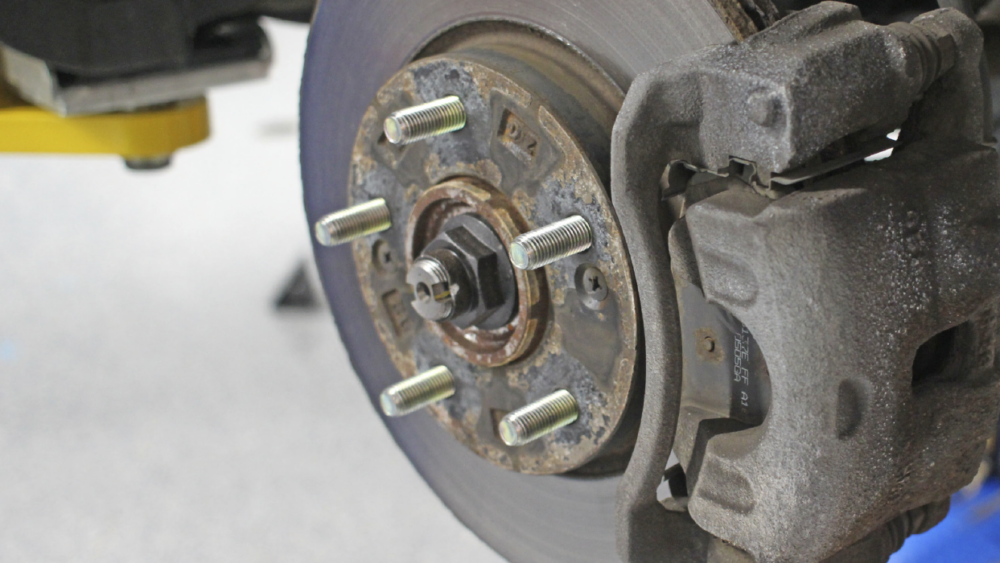
People generally equate a high runout value with “warping.” In reality, runout by itself is not a direct or sole generator of pulsation. The characteristic that most directly generates roughness is actually Disc Thickness Variation (DTV). This measurement is the result of measuring the thickness of the rotor braking surface at multiple spots around the rotor.
The DTV is the largest (thickest spot) minus the smallest (thinnest spot) of the rotor. This action of thick and thin spots passing through the caliper generates the BTV mentioned previously. When the thick part of the rotor is forcing itself through the caliper, the torque of the brake and the pressure in the caliper rise.
When the thin spot passes through, the torque and pressure drop. Very small amounts of DTV can create a significant problem. Today, new vehicles are typically built with a thickness variation of less than 0.00078”. Thickness variations in excess of 15 microns (0.00059”) can easily generate driver complaints.

Red and Black Rust
The other condition that can occur is a variation in the friction of the rotor around its circumference. If the rotor has a slippery spot or a sticky spot relative to the rest of the part, a variation in torque will result (even with zero DTV). Variations in friction will generally be the result of corrosive or contamination effects. While there will generally also be thickness variation, it is possible to have friction variation without the thickness variation.
Friction variations can occur when a vehicle has sat undriven for extended periods of time. (Perhaps while the driver was on vacation or if the vehicle sat on the dealer’s lot before sale.) Most friction materials will self-clean red rust. The more difficult issue is “black rust,” chemically known as FE3O4, it is an iron oxide that is very hard. The source of this oxide is heavily debated, but once present, turning rotors or replacement are generally the only available options.
The DTV/LRO/BFV Relationship
It is often suggested that lateral runout is the cause of pulsation. High LRO generates the picture of a warped or “potato chipped” part. However, lateral runout by itself generally will not exhibit pulsation. To have pulsation, DTV or friction variation must also be present. Thickness variation will develop when the rotor wears non-uniformly. Runout will allow a portion of the rotor to “kiss” the pad when the high spot comes by.
If the pad has the opportunity and ability to abrade the rotor, localized wear will occur on only one side of the rotor. Over time, the high spot will get machined down, which will result in a thin spot developing. By the time the pulsation appears, it is very common to find that the runout has dropped to a very small value. Essentially, the runout has been machined out. As the runout drops, the thickness variation grows.
Generally, there is a strong relationship between the amount of initial runout and the likelihood that pulsation will develop in the future. As a result of this strong relationship, a great deal of technology is employed in today’s vehicles to control and minimize this.
The Total Picture
As mentioned previously, today’s vehicles generally have less than 50 microns (or .0019”) of runout with the wheel mounted. To achieve values of this level, the entire wheel end must be developed as a system.
Integrated or unitized hub and bearing units are generally employed. This allows the hub face to be machined together with the bearing, resulting in substantially lower runout than when the hub and bearing are manufactured separately and randomly.
Many bearings will actually have a machined step in the region the wheel studs are installed. This masks the localized “volcanoing” that occurs in the material around the stud. This micron (1 micron=.000039”) level volcanoing will distort the rotor when the clamp load of the wheel is applied. Sophisticated torque sequence strategies for the lug nuts are also employed to ensure a uniform clamping of this joint.
The “wheel mounting interface” is also strictly controlled and matched to the hub and rotor design. All of these features are subtle and exist in the single-digit micron domain. They must all be in proper condition to reliably establish and maintain the runout in the wheel end. Cleanliness of the joint or mating surfaces is critical. Even minor contaminants like corrosion or metal chips from an on-the-car brake lathe can generate measurable LRO on the rotor.
This becomes a consideration when changing wheels in the aftermarket. In a great many cases, an aftermarket wheel will not be designed to achieve the subtle features or stiffness necessary to contribute to low lateral runout. When installing new wheels on a vehicle, it is highly recommended that the lateral runout be measured and set on the vehicle.
Shim kits are commercially available and are an effective way to tune or dial in the runout. This simple step can help prevent or delay the occurrence of roughness complaints.
The question is often raised whether the aftermarket can deliver the types of tight tolerances mentioned in this article to its parts and shop service equipment.
The answer is a qualified, “Yes.” I have performed studies measuring rotors turned with both on-car lathes and standard lathes. Both have demonstrated the ability to deliver very acceptable results. However, I have also witnessed cuts that sent the part out worse than when it came in. Like most things, it comes down to operator training and machine condition. The operator should always confirm the condition after turning. This takes minimal time and increases confidence in a quality repair.
Roughness is a very complicated condition and the control of this relies on the ability to produce and maintain parts to surprisingly tight tolerance for a bunch of iron bouncing down the road through every pothole and puddle. By understanding the critical interactions and the nature of the condition, the technician can have success providing a quality, long-lasting repair.
Article adapted from Brake & Front End.