 It’s important to know that, although electric power steering (EPS) has been introduced on many 2004-and-later domestic applications, EPS has also been appearing on popular import nameplates since the 2015 models. Not to be confused with electro-hydraulic steering, in which a hydraulic power steering pump is driven by an electric motor, electric steering is a non-hydraulic system assisted by an electric motor operated by a software-driven power steering module. EPS should also not be confused with a “drive-by-wire” system in which steering motors directly replace mechanical steering linkages. In contrast, EPS merely provides an assist function to conventional steering gears and linkages.
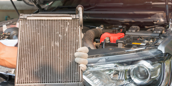
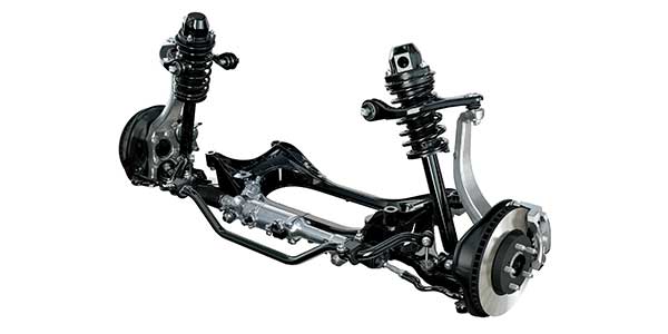
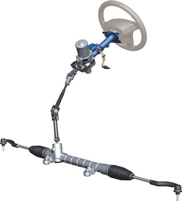
EPS has several configurations, including an electric assist motor integrated with the rack-and-pinion steering gear (see photo at top).
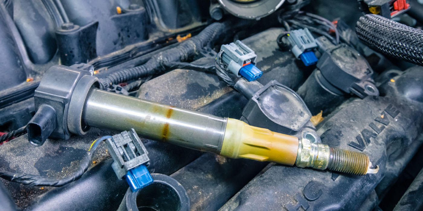
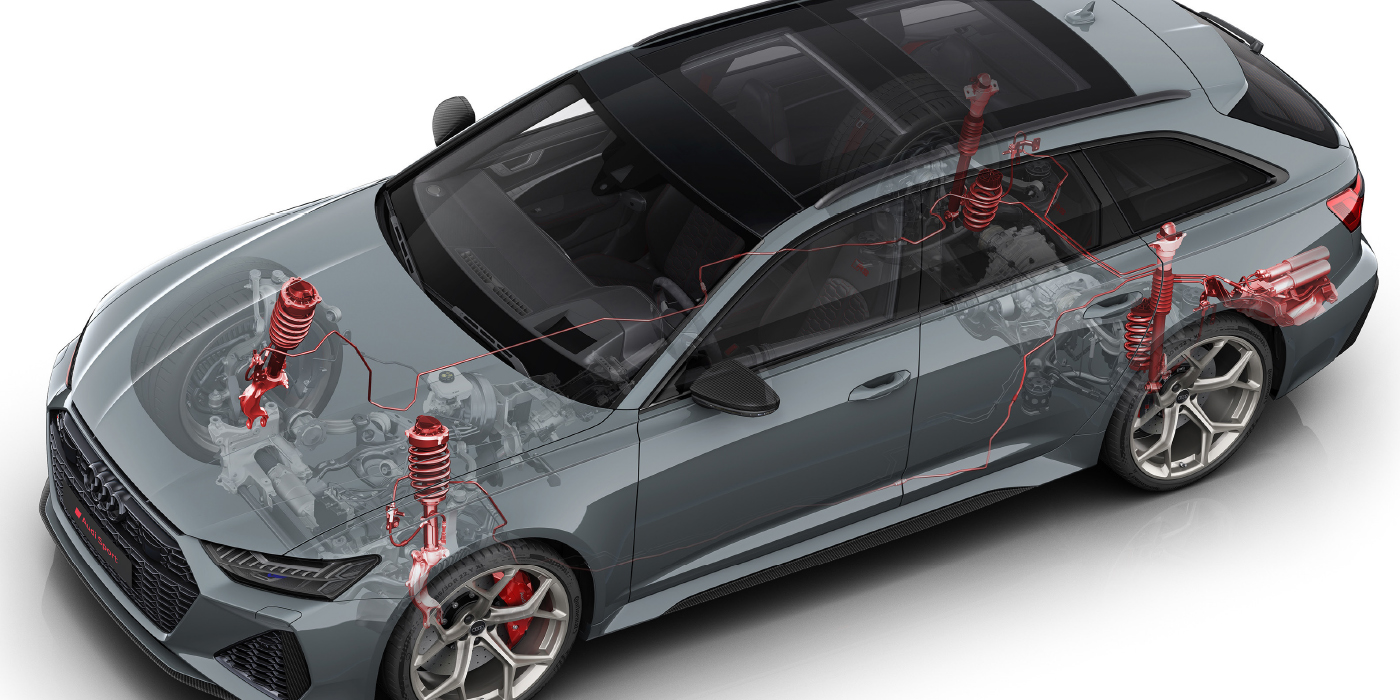
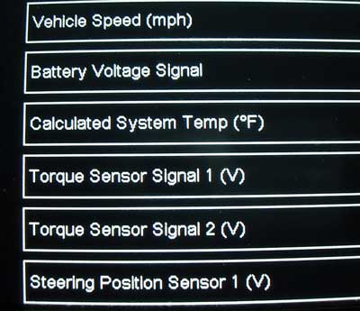
In another configuration, the EPS assembly is inserted between the steering wheel and the steering rack (see photo above). No matter what the configuration, the power steering control module receives inputs from a steering position sensor and a steering torque sensor that is mounted on the steering rack input shaft.
The EPS control module also receives a vehicle speed input that, in combination with the steering position and torque sensors, combine to produce steering feedback to the driver. The position and torque sensors might also provide an electric input to safety-related systems like the vehicle stability control system (VSC), if so equipped.
STEERING GEAR BASICS
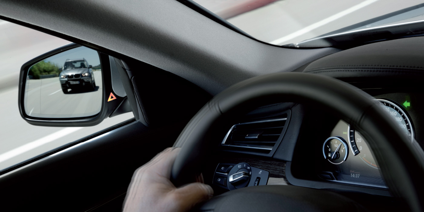
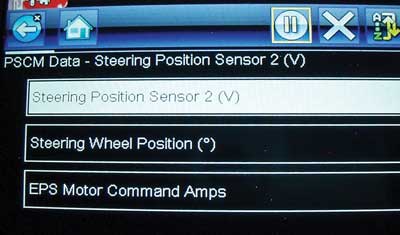
For the driver to feel comfortable driving a modern automobile, the steering gear must transmit steering feedback to the driver through the steering wheel. No matter how precise the alignment, if the steering gear doesn’t transmit a “center point” or “steering” feedback through the steering wheel (see scan tool screen capture 1), the driver might complain of steering wander or a steering system that “just doesn’t feel right.” In many cases, the loss of “steering feedback” might be attributed to the alignment or to wear in the steering gear and linkage system. For electronic steering applications, several import manufacturers have issued recalls for reprogramming the software that creates a better steering feedback for the driver (see scan tool screen capture 2).
To better understand how a steering gear might affect steering feedback, let’s examine how a manual steering gear achieves that goal in many early imports. The concept is relatively simple: Torque created at the steering wheel is transmitted to the steering gear via the steering shaft. The steering shaft is connected to a worm gear that bears against a sector gear in the steering box. The sector gear not only converts the rotary motion of the steering wheel into a side-to-side motion that steers the vehicle, it also multiplies the torque created by the steering wheel.
The rack-and-pinion steering gear is a more current steering system that was popularly introduced during the late 1960s. The rack-and-pinion steering gear, or steering rack as it’s more popularly known, replaced the more complex “parallelogram” steering system of steering gear, pitman arm, idler arm and drag link. The steering rack concept results in a more precise steering system that doesn’t contain as many moving parts.
STEERING FEEDBACK
The conventional steering gear provides “steering feedback” by machining the worm and sector shaft gears to provide a slight preload halfway between full right-hand and full left-hand steering positions. This preload creates feedback to the driver as to when the steering gear is at center point. As the steering gear rotates from right or left, the clearance between the worm and sector gears increases, which transmits a sense of steering wheel position to the driver. As the steering gear wears, the worm and sector-shaft gears begin to lose their center-point preload. The result is a loss of steering feedback that eventually develops into a case of steering wander.
Manual rack-and-pinion systems provide steering feedback by machining their pinion and rack gears in the same manner. To steer correctly, all four wheels must be aligned in relationship to the thrust centerline of the vehicle. The steering gear is then aligned to the thrust centerline by adjusting individual toe angles on the front wheels.
ELECTRIC STEERING SYSTEMS
Since many electric steering systems aren’t field serviceable, they are usually replaced as a unit. In other configurations, the EPS module, steering torque and steering position sensors can be individually replaced. Although configurations might vary, the basic electric steering system consists of the power steering control module, assist motor, torque sensor and steering position sensor. As mentioned above, the torque and steering position sensors might also provide inputs to other systems, including the vehicle stability control system. The beauty of electric steering is that all of the steering feedback functions are incorporated into the power steering module, which allows the system to be fine-tuned by reprogramming the module’s software.
EPS DIAGNOSTICS
As mentioned at the outset, the primary EPS data inputs include voltage signals from the torque sensor and steering position sensor and a vehicle speed input — generally from the ECM — to the power steering module. The vehicle speed input modulates steering sensitivity in relation to vehicle speed. The electromechanical assist is usually a directionally controlled, pulse-modulated electric motor that is geared into the steering shaft.
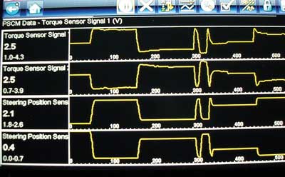
Diagnostics on any EPS system should begin by scanning the EPS module for diagnostic trouble codes. For example, a “C-series” code indicates problems within the feedback and electromechanical assist portions of the system. A “U-series” code indicates a data-sharing problem between the EPS, ECM, ABS and other system modules. To illustrate, a 2014 Toyota Camry would set a C1511 code if the steering position sensor doesn’t produce a rational input voltage. A C1521 code would set if a motor malfunction (loss of steering assist) occurs (see scan tool screen capture 3.) The voltages produced by the torque and steering position sensors are positive and negative values that mirror each other and are similar in function to those produced by an electronic throttle. When graphed with each other, they intersect at specific intervals, which allows the EPS module to rationalize voltage inputs and set various trouble codes. Since some manufacturers are experiencing some no-code steering feedback and intermittent assist-failure problems, it always pays to review manufacturer recall notices and technical service bulletins for replacement or software reprogramming issues.
Electronic steering diagnosis isn’t complicated, but can require vehicle-specific module programming and reprogramming capabilities. For many, module reprogramming remains another technical hurdle to be cleared. Nevertheless, module programming is now becoming an everyday occurrence in the modern world of steering system diagnostics.