igue; 1995-’99 Pontiac Bonneville; and 1997-’99 Pontiac Grand Prix with the 3.8L engine.
 Note: This bulletin, issued in September 2007, is being revised to add to the 1999 model year. You should discard the previous GM Corporate Bulletin Number 01-06-01-007B (Section 06 – Engine).
Condition: Some customers may comment on excessive engine coolant consumption, or an engine coolant leak near or under the throttle body area of the upper intake manifold.
This could be related to upper intake manifold composite material that may degrade around the EGR stove pipe and could result in an internal or external coolant leak.
To make the repair, follow the upper intake manifold removal instructions found in the Engine Unit Repair section of the service information manual.
Refer to the arrow in the illustration of the upper intake manifold (see Figure 1). Inspect the inner diameter of the EGR passage for signs of material degradation. Degradation will appear as “pitting” of the composite material in the EGR port passage.
If degradation of upper intake manifold composite material is found, replace the lower and upper intake manifolds with the following part numbers:
Part Number Description
89017554 Gasket Kit, Upper Intake Manifold
89017272 Manifold Kit, Upper Intake
89017400 Gasket, Lower Intake Manifold
24508923 Manifold, Lower Intake
Follow the lower and upper intake manifold installation instructions found in the Engine Unit Repair section of the appropriate service manual.
If degradation is not apparent, evaluate the vehicle for other causes of excessive coolant consumption as noted in the Engine Diagnosis section of the appropriate service manual.
Revised Crankshaft Balancer Service Procedure
Next up, you may have an engine that requires service to the crankshaft balancer on the following vehicles: 1995-’96 Buick LeSabre, Park Avenue, Regal, Riviera; 1995 Chevrolet Lumina APV; 1995-’96 Chevrolet Camaro; 1995 Oldsmobile Silhouette; 1995-’96 Oldsmobile Eighty-Eight, Ninety-Eight; 1995 Pontiac Trans Sport; 1995-’96 Pontiac Bonneville and Firebird with 3800 engines.
Be advised that the procedure used to service the crankshaft balancer has been revised. Use the following procedure to properly service the crankshaft balancer on these engines.
According to GM, there has been a running design change in the crankshaft balancer. This change affects 3800 engines built late in the 1995 model year (L27 and L36) and all of 1996 model year (L36 and L67). Refer to the appropriate section in the service manual if you have the previous design crankshaft balancer.
Refer to the following procedure using (J 38197-MOD) for the revised design crankshaft balancer. The crankshaft
balancer designs can be easily identified by a dimple stamped in the face of the crankshaft balancer (see Figure 2, view B). This dimple aids in the alignment of J 38197-2 and also identifies the crankshaft key location in relation to the slot in the crankshaft balancer.
The special tool (J 38197) and the service procedure used to service the previous design crankshaft balancer have not been revised. Refer to applicable service manual and section for correct service procedures.
For the revised crankshaft balancer design, you will see a round hole drilled in the face of the crankshaft balancer (see Figure 2, view A).
This hole does not aid in the alignment of J 38197-2, like the dimple on the previous designed crankshaft balancer. The hole is used to identify the crankshaft key location in relation to the slot in the crankshaft balancer. The special tool (J 38197) has been revised to reflect the design changes and the new tool is J 38197-MOD.
(If you already have J 38197, it is necessary to only order the J 38197-MOD). The revised crankshaft balancer requires the use of three bolts (J 38197-4).
Note: These bolts are 1/4” longer than the previous design. The J 38197-4 bolts are silver, while the previous tool uses black bolts.
Note: The J 38197-4 tool should not be used to service the previous design crankshaft balancer as damage to the balancer may occur by using the longer bolts.
The revised crankshaft balancer may have burrs on the slotted access holes that do not allow the proper alignment of J 38197. If burrs are present, remove them by using one of the following methods:
• File the access hole using a rat-tail file in the proper location.
• Drill an access hole using a drill in the proper location.
• Bend the access hole using a screwdriver in the proper location.
Removal Procedure
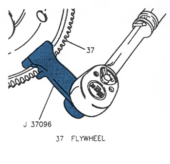
1. Hold the flywheel using J 37096 (see Figure 3).
2. Locate the crankshaft balancer bolt.
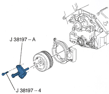
3. Remove the crankshaft balancer using J 38197-A and J 38197-MOD (see Figure 4).
a. Invert the J 38197-2 so that the leg of the tool is facing away from the crankshaft balancer.
b. Install the silver screws (J 38197-4) to the crankshaft balancer.
c. Turn the J 38197-1 to remove the crankshaft balancer from the crankshaft.
d. Remove the J 38197-1, 2 and 4 from the crankshaft balancer.
Important: The crankshaft balancer is serviced as an assembly. Do not attempt to separate the pulley from the balancer hub.
Tools Required
J 36660 Torque Angle Meter
J 37096 Flywheel Holding Tool
J 38197-A and J 38197-MOD Crankshaft Balancer Puller
J 38197-A Includes:
J 38197-1 Pilot Screw
J 38197-2 Puller Plate
J 38197-3 Puller Screws (Black)
J 38197-4 Puller Screws (Silver)
J 38197-MOD includes:
J 38197-4 Puller Screws (Silver)
Installation Procedure
1. First, lubricate the crankshaft and the inside of the balancer with clean engine oil.
2. Line up the crankshaft balancer using the small hole to aid in the alignment of the crankshaft key.
3. Install the crankshaft balancer bolt and hold the flywheel using J 37096.
4. Tighten the bolt to 150 Nm (111 lb.-ft.) + 76° using J 36660.
Source: ALLDATA