 Understanding The Function of Serial Data Buses

If serial data buses did not exist, a wiring harness would have to be five times its normal size and use twice as many sensors to deliver the same level of functionality and safety we see in the modern vehicle. For example, take a brake pedal sensor. On a modern vehicle, the position of the brake pedal is used by the shift interlock, ABS system, cruise control, traction control, brake lights and electric emergency brake. If each system required its own switch and wiring, the complexity of the wiring harness and switches would be a diagnostic nightmare.
Serial data buses also help to eliminate multiple sensors and wiring. One sensor can share information with multiple modules without having to connect directly to the multiple modules.
Serial data buses may seem like a daunting concept to some technicians, but understanding them is now a required skill to work on most modern vehicles.
What is On The Serial Data Bus?
A serial data bus uses voltage to communicate. Modules toggle the signal off and on, making the 1s and 0s of digital binary language like Morse code. This code can communicate commands that allow something as simple as rolling up a window or as complex as stability control correction.
Zero volts on any serial data bus is translated into binary language as “1,” and when the voltage increases the voltage to a specified level, it equals “0.” Most electronic devices operate on signals toggling between 0 and 5 volts. This includes laptops, DVD players and PCMs.
 On most automotive serial data buses, the peak voltage level might be 7 volts. This extra voltage is to accommodate resistance in the wires and ground problems that may cause voltage drops. The extra 2 volts gives the network a safety buffer that may help the vehicle as it ages.
If a signal was on an equal length of time as it was off, you would have 0, 1, 0, 1, 0, 1 as the binary message being sent out. It could represent what the throttle position voltage is, a signal being sent from the airbag module to the BCM reporting the status of a sensor.
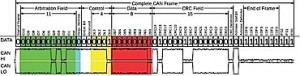
This could be a either a J1850 or CAN-Hi bus. Whatever the bus message, it’s comprised of 0s and 1s, or the states of highs and lows. Some systems use a variable pulse width that not only toggles between on/off, but can transmit additional information by varying the length of time the voltage is either on or off. This is how all serial data buses operate.
Binary Speed
What separates the earliest serial data bus from a modern CAN bus is how fast the system can toggle between 0 and 5 volts. The faster the switching, the more information can be transmitted in a given amount of time. Modern buses are able to do this with better software and with hardware that can interpret the signals with faster processors.
Faster speeds are needed so the ABS and PCM modules can communicate quickly if a stability control correction needs to be made that involves closing the throttle and applying the brakes.
Serial Data Bus Practical Diagnostics
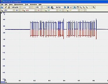
You are never going to be able to look at the signals on a scope, decipher a series of 1s and 0s, and say that it is a command to turn on the brake light. What it can tell you is that a module is communicating and the bus is active.
But, the most critical skill for working on serial data buses is learning how to read the wiring diagrams to figure out how modules and sensors are structured on the bus.
In the auto repair world, the term used to describe the design, layout and behavior of a serial data bus configuration is “topology.”
Reading the Wiring Diagram
As a technician in the modern vehicle era, you’re going to need to understand these “bus lines.” The dotted line at the edge of the component, node or module indicates where the CAN bus enters and exits.
Some schematics may include other information in the boxes with two arrows pointing in opposite directions. All two-wire CAN bus lines terminate in a resistor(s) of a known value. This is what produces the correct amount of voltage drop.
Bus Configurations
There are three types of bus configurations that you will come in contact with — loop, star and a hybrid of both.
In a loop system, the topology of the nodes or modules is connected electrically in parallel.
Each node has two wires that connect it to the bus. This system multiplexes the nodes together so information can be shared along one circuit. With this system, all of the nodes can turn on a check engine light in the instrument cluster through the use of information within the circuit.
Each of these modules can communicate something to another module. For example, the HVAC would want to communicate with the BCM to ask permission of the PCM to turn on the compressor clutch by energizing the relay.
If you had an open circuit between the BCM and PCM, the PCM could still communicate to the BCM, although it would have to go through the other modules. Communication still takes place if you have one open circuit.
But, if you had two open circuits between the BCM and PCM, and an open circuit between the IPC and radio modules, the PCM would be isolated and would not be able to talk to the BCM or the ABS module.
Shorts in a Loop
The problem with a loop during diagnostics is if a short circuit occurs. The loop configuration can be easy to diagnose because even with two open circuits, nodes are isolated off the bus. But in a short circuit, with the modules in parallel, the whole circuit goes down.
When a bus shorts, it can be a difficult process to isolate the offending module or section of wiring. In a case where a module shorts out the bus, you would literally have to unplug them one at a time to see which module eliminates the short circuit. That would not be a good scenario in the repair world because it would take a lot of time to gain access to those modules.
Shorts are one disadvantage of the loop configuration. The advantage is you have a redundancy of wires. Therefore, these are more impervious to an open circuit issue.
Star Bus Configuration
The star configuration’s topology uses a comb, butt connector or shorting bar. It plugs into a female connector.
All of the modules have a single wire coming out of them on the serial data bus leading to that one common connector that would tie them all together in parallel.
The star configuration got its name from the computer industry. For example, an Ethernet connection is a star configuration with computers, printers and servers all connected to an Ethernet hub.
Star connectors are often located near the DLC, but note that there are exceptions. And, some manufacturers solder them in place while others don’t, allowing for the connector to be removed a lot easier. On some vehicles, the star connector can be removed and a meter can be connected to each circuit to test for shorts to power or shorts to ground.
Loop/Star Hybrid Versions
Automakers may also combine both loop and star topologies in a single-bus system.
They may wire them in a combination of both the star and the loop configuration where both systems have a number of nodes on them that talk on the loop and star.
If you know the theory on how this type of bus works, and there is a short to ground or power, the next step is to remove the splice packs and check the nodes.
If the short goes away, the next step is to unplug modules one at a time to see if that short comes back.
If the short is still present with the splice packs removed, it could be the nodes in the loop configuration. In this case, the ABS and instrument cluster modules might be a source of the short to ground or power, and are connected to the splice pack.
To eliminate them as the possible source of the problem, you’ll need to unplug and check these modules one by one.
Being able to recognize whether the topology is a loop, star or hybrid configuration will make testing and diagnosing shorts, grounds and communication errors faster and more effective than using steps and flow charts.
Knowing how both shorts to opens and normal shorts (power and ground) behave on a loop or star can help you formulate a more effective plan of action so you can do more in less time.
Bus Connection in the DLC
Since 1996, all vehicles sold have a diagnostic connector under the dash. Some pin assignments are standardized across all vehicles. Some pins assignments are left up to the manufacturer.
PIN 1: Manufacturer discretion. GM: J2411 GMLAN/SWC/Single-Wire CAN
PIN 2: Bus positive line of SAE-J1850 PWM and SAE-1850 VPW
PIN 3: Ford DCL(+) and Chrysler CCD (+)
PIN 6: CAN HI (ISO 15765-4 and SAE-J2284)
PIN 7: K line of ISO 9141-2 and 14230-4
PIN 10: Bus negative line of SAE-J1850 PWM only (not SAE-1850 VPW)
PIN 11: Ford DCL(-) Argentina, Brazil (pre OBD-II) 1997-2000, USA, Europe, etc. Chrysler CCD Bus(-)
PIN 14: CAN low (ISO 15765-4 and SAE-J2284)
PIN 15: L line of ISO 9141-2 and ISO 14230-4
Courtesy Underhood Service.