 Cars just keep getting smarter all the time. Sensors are being used to monitor more and more functions, and to share information between vehicle systems that formerly were mute or didn’t communicate with one another. One such sensor is the steering position sensor. The sensor’s basic function is to monitor the
driver’s steering inputs. This includes the angle of the steering wheel and/or the rate at which the driver is turning the wheel.
Early Applications
In the 1980s, automakers introduced the first generation of variable-assist power steering systems. The simplest of these systems used a solenoid on the steering rack to reduce hydraulic power steering assist when the vehicle was traveling faster than a certain speed (typically above 20 to 25 mph). Reducing power assist as the speed increased improved road feel and steering stability. The only sensor input required for these systems was a vehicle speed sensor signal.
The more sophisticated variable assist power steering systems added a steering sensor to override the cutout solenoid when the driver made a sudden steering maneuver. The Ford Variable Assist Power Steering (VAPS) system on the 1988 Lincoln Continental and the Electronic Variable Orifice (EVO) power steering system on the 1989 Thunderbird and Mercury Cougar both used a steering sensor for this purpose.
On these early Ford systems, the steering sensor functioned only as a rotation sensor. It did not measure the angle of the steering wheel, but only the rate at which the steering wheel was being turned by the driver.
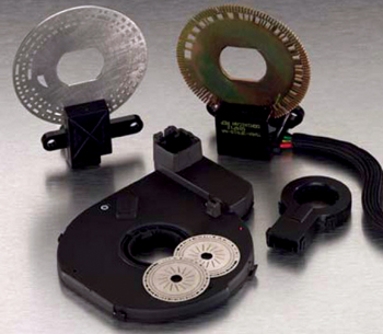
Most of these early generation steering sensors were optical sensors with photo diodes inside that read evenly spaced slits in a disc attached to the steering column. Turning the steering wheel to either side generates a pulse signal that goes to a steering control module. On the Ford VAPS system, the control module ignores the steering inputs as long as the driver is making relatively slow steering motions (less than 90° of rotation per second). But if the driver turns sharply or swerves, the control module reacts by reducing current to the cutout solenoid to increase steering assist.
In the event of a steering sensor failure, most the system was designed to fail-safe with full power assist remaining on regardless of vehicle speed, steering angle or rate of rotation.
If you find yourself troubleshooting one of these older systems, most of the diagnostic checks on the steering sensor will be made with an ohmmeter. Measuring the resistance between the sensor’s connector pins and comparing the values to specifications will tell you if the sensor is good or bad. On some applications, an analog ohmmeter can be used to detect pulses from the sensor as the steering wheel is rotated with the key on.
More Sensitive Sensors
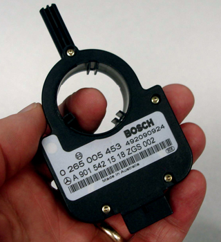
Most of the early steering position sensors are relatively low-resolution sensors, and typically detect steering movements in 8° to 9° increments. By comparison, most of today’s steering position sensors are high-resolution magnetic sensors that can detect movements of 1° or less. Some have resolutions as low as one-tenth of a degree!
 Why the Change in Sensitivity?
Steering angle sensors are used for a wider variety of purposes today, and for fast-acting stability control systems to react instantly to changing driving conditions, the system must be able to detect even small changes in the position of the steering wheel. Engineers know that the angle of the front wheels as well as the steering inputs by the driver have a significant impact on vehicle dynamics, handling stability and traction.
Advances in onboard computing power in recent years and system integration and information sharing via local area networks (LAN) and controller area networks (CAN) now make it possible for various systems to share information and sensor inputs. Consequently, the inputs from a steering position sensor can be used to vary power steering assist, to modify anti-lock braking and traction control, to assist stability control, to modify the reaction of an electronic suspension system, to modify torque delivery in an electronic all-wheel-drive system, and to even monitor the driver himself.
The steering position sensor also will play a key role in future accident avoidance systems that detect obstacles and steer the vehicle to avoid the obstacle if the driver fails to react.
Down the road, the steering sensor may even be used to monitor the driver. Engineers are now developing systems that detect subtle changes in the driver’s steering inputs to determine if the driver is impaired or not. The system “learns” the driver’s normal steering habits, and sounds an alarm (or disables the vehicle) if the driver is steering erratically. Who would have thought Big Brother might someday be lurking inside your steering column?
Diagnostics
Because stability control is part of the ABS system, faults are self-diagnosed and turn on one or more warning lights. Depending on the nature of the fault and the application, a steering position sensor failure may disable the stability control system and/or ABS system.
Diagnostics require the use of a scan tool on most vehicles, and the scan tool must have the appropriate software that can access the stability control/ABS system. If you find a steering position sensor code, you’ll have to follow the diagnostic charts to isolate the fault as the problem may be in the wiring or the sensor itself.
 In magnetic sensors, there are no moving parts so the units are fairly reliable. Even so, faults may occur in the internal electronic circuitry that processes and generates the sensor’s output signal. Loss of voltage or ground can prevent the sensor from functioning properly, so wiring faults should be ruled out before replacing the sensor. The sensor itself is a sealed assembly and is not repairable or rebuildable.
Some steering sensors have their own built-in self-diagnostics and will generate a warning signal to the stability control system or body control module if it detects any internal faults. The stability control system or body control module may also set a fault code if the signal from the steering position sensor is lost or is out of range. The system may also compare the steering angle reading against the yaw sensor when the vehicle turns to see if the signals correspond.
Depending on the vehicle application and scanner software, it may be possible to read the steering angle through the scan tool. This would allow you to rotate the steering wheel and look for a corresponding change in the indicated steering angle.
Steering Sensor Precautions
Steering sensors are located in the steering column typically behind the turn signal assembly. The sensor may be integrated with the clockspring assembly for the air bag system, but it is usually a separate component. Access requires disabling the air bag system and removing the steering wheel and turn signal assembly.
On some vehicles, the steering sensor must be aligned or recalibrated if it is removed or replaced. On some vehicles, this procedure is relatively simple, but on others it requires the use of a scan tool with the appropriate software.
On some of the older Mercedes applications, the steering angle sensor is initialized by turning the ignition to RUN, and rotating the steering wheel lock to lock.
On Cadillacs and other GM vehicles with Stabilitrak, some steering position sensors have alignment marks that must be aligned before the sensor is removed. The location of these marks will vary depending on the sensor, model year and vehicle. Some replacement sensors have a locator pin that is used for alignment. The details are covered in GM TSB 03-02-36-002.