Adapted from Gary Goms’ article in ImportCar.

For many years, most of us believed that the mass airflow system provided the most accurate measurement of an engine’s intake airflow. For one thing, not too many things can go wrong with a system that produces a single voltage or frequency input that indicates to the ECM an exact value of intake airflow in grams per second. In contrast, a typical 1980s speed density system estimated intake airflow by using inputs from the intake manifold absolute pressure/barometric (MAP/Baro), throttle position (TP), engine coolant temperature (ECT), intake air (IAT) and engine speed (RPM) sensors.
Since a speed density system has so many parts that can fail or drift out of calibration, imagine my surprise when I recently read that some of Ford’s new world-class EcoBoost engines are now equipped with speed density engine management systems!
NEW ENGINE TECHNOLOGY
Modern engine technology is changing our concept of how we increase engine torque and fuel economy. Ford Motor Company has, for example, reduced rotating friction in its EcoBoost series by reducing cylinder displacement and by using roller-type bearings to support its dual overhead camshafts. Ford also has reduced rotating mass by eliminating balance shafts and their related rotating parts.
Other engine designs reduced rotating mass by incorporating a flat-plane 180º crankshaft that doesn’t require heavy counter-balance weights. To reduce engine warm-up times, water-cooled engine exhaust manifolds are now cast integral to the cylinder head, with responsive turbochargers mounted directly to each manifold. Modern engines like the EcoBoost also use variable exhaust valve timing to eliminate conventional exhaust gas recirculation (EGR) systems.
When these new technologies are coupled with current technology like wide-band air/fuel ratio sensors, electronic throttle controls with double-redundancy throttle position sensors, variable intake valve timing, direct fuel injection, pulse-modulated fuel pumps and much faster computing capabilities, we’re looking at some major advances in producing high engine torque, increasing fuel economy and reducing exhaust gas emissions.
MAF SENSOR ISSUES
To better understand the evolution of the modern speed density system, let’s take a brief look at the conventional hot-wire mass airflow (MAF) sensor.
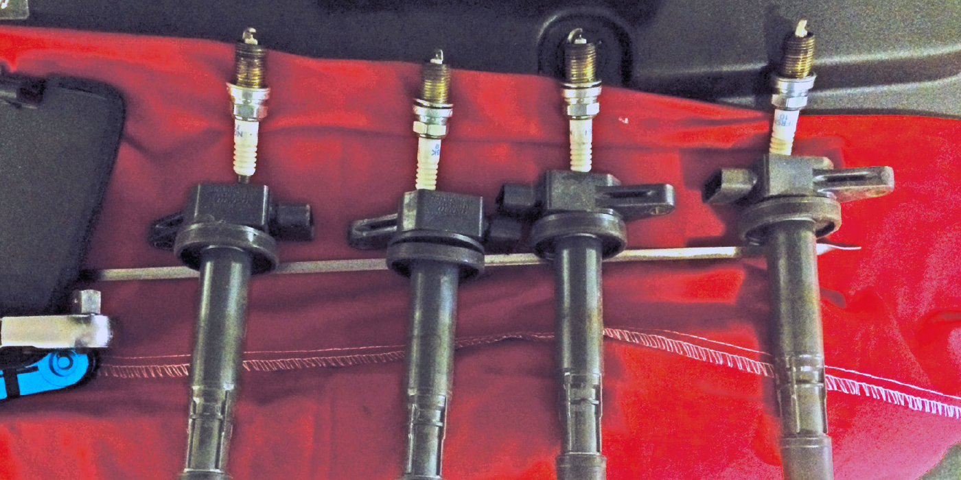
At its most basic level, the conventional hot-wire MAF sensor relies on the cooling effect that fast-moving air has on a “hot wire” resistor suspended in the air stream (see Photo 1). In short, the faster the air mass flowing past the hot wire, the cooler the wire becomes. The cooler the wire, the greater the amperage flow through the hot wire. The MAF then translates this amperage value into a direct voltage or a frequency (Hz) value indicating grams-per-second airflow to the ECM. To aid in this computation, an IAT sensor is integrated into the MAF sensor.
In other MAF configurations, a Baro sensor is added to report key-on, engine-off baro, while in conventional MAF configurations the barometric pressure value is calculated as the engine accelerates. The downside of the MAF sensor is a vulnerability to air-borne dirt and fibers caused by improperly installed air filters.
Since any type of airborne debris produces either an insulating or a radiating effect on the hot wire, a positive or negative air/fuel calibration error occurs as dirt accumulates on the MAF’s hot-wire resistor. The most common indications of a dirty MAF sensor are an incorrectly calculated barometric pressure, an incorrectly calculated engine load and abnormal fuel trim values.
MAP/BARO VALUES
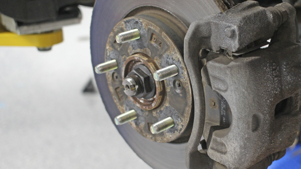
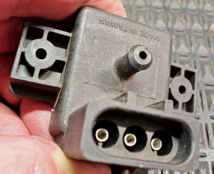
The MAP/Baro sensor reports the vehicle’s operating altitude (barometric pressure) to the ECM at key-on, engine-off (KOEO). While weather conditions and intake air temperature will modify the MAP/Baro reading somewhat, a typical KOEO baro is 29.5 inches of mercury (29.5” Hg) at slightly above sea level. At an altitude of 8,000’, a typical KOEO Baro is 22.5” Hg. See Photo 2.
At idle speed, the MAP/Baro reports manifold absolute pressure, which is the barometric pressure inside the intake manifold. MAP might be expressed on a scan tool datastream either as a pressure differential or as conventional intake manifold vacuum. At sea level, 29.5” Hg KOEO and 22.5” Hg key-on, engine-running (KOER) might be displayed as a -7.0” Hg pressure differential. Some scan tools might interpret that same data as +22.5” Hg “intake manifold vacuum.”
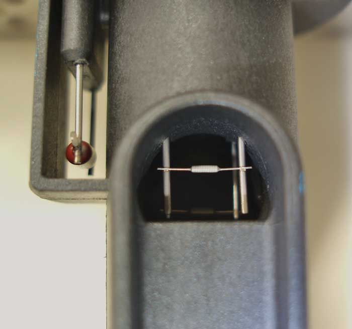
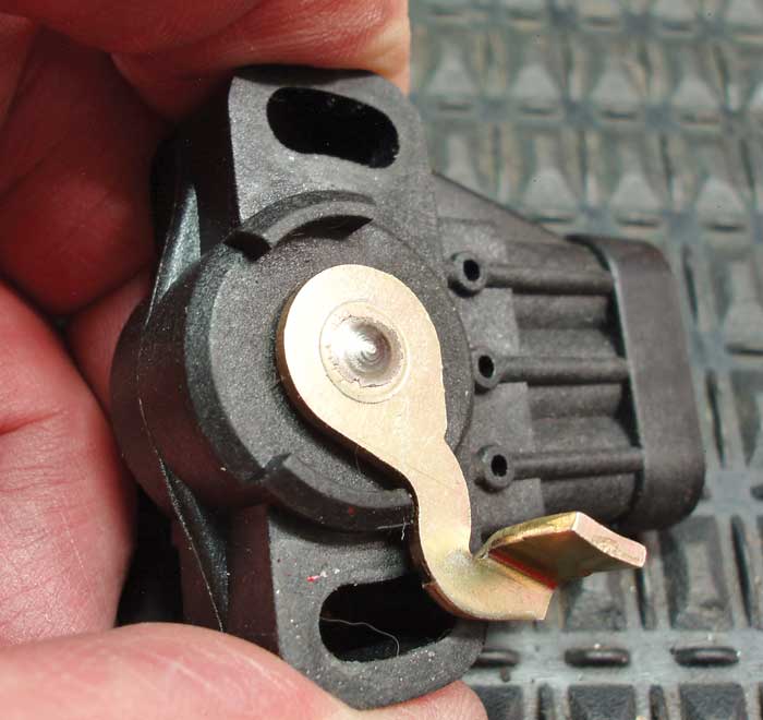
Because the new generation of engines will likely be turbocharged, MAP values will range well above atmospheric and, for that reason alone, it’s better to think in terms of MAP than vacuum. See Photo 3.
SPEED DENSITY
If you’ve experimented with an older speed density system by attaching a vacuum pump to the MAP/Baro sensor vacuum line to make minor changes in the reported MAP values, you quickly realize how sensitive the engine’s fuel control system is to MAP. The speed density system’s ability to instantly respond to changes in air density downstream of the throttle plate is crucial for making fast and accurate air/fuel ratio calculations.
More important, when the engine is running, air density inside the intake manifold is partly controlled by throttle plate position.
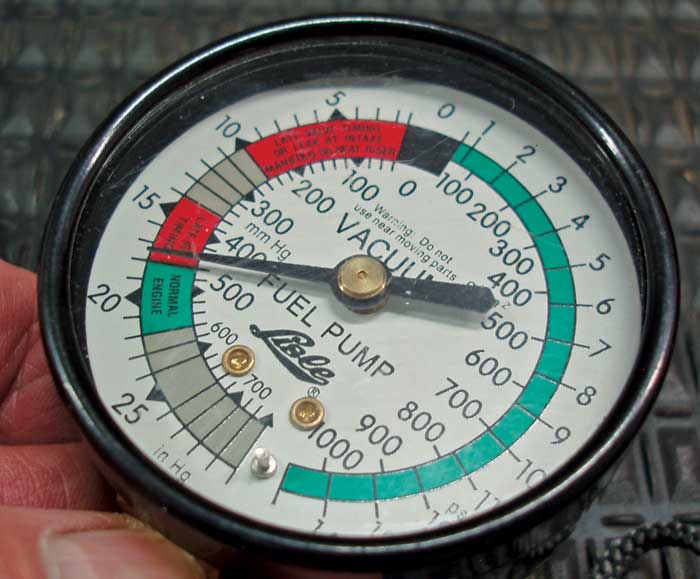
To illustrate, at wide-open throttle peak engine speed, MAP inside the intake manifold is nearly equal to the outside barometric pressure. At closed-throttle idle speed, MAP inside the intake manifold (ex. 22.5” Hg) is considerably less than barometric (29.5” Hg). At part throttle, MAP is largely dependent upon engine load. MAP pressure will become more equal to barometric as engine load is increased at a fixed throttle position.
In contrast, MAP pressure will become less equal to barometric as engine load is reduced at a fixed throttle position. With these issues in mind, we might catch a glimpse of why a modern turbocharged, variable-valve timing engine might be better served by a speed density system than a traditional mass airflow system. See Photo 4.
MODERN SPEED DENSITY ADAPTATIONS
With a few added refinements, the speed density system might perform more reliably on modern engines than mass airflow systems. As mentioned earlier, the MAP/Baro sensor speeds up the air/fuel computation by instantly responding to changes in MAP. To further refine the system, many speed density configurations separate the MAP and Baro functions. The Baro sensor might, for example, be built into the ECM circuit board.
On some applications, the MAP sensor might measure a broader pressure range than the barometric pressure sensor. A broad-range MAP sensor can be used to not only indicate MAP, but turbocharger boost pressure and turbocharger exhaust backpressure as well. And, on some EcoBoost applications, the IAT sensor might be combined with the MAP sensor. At KOEO, the ECM might monitor sensor calibration by comparing or rationalizing Baro, MAP and boost pressures.
When operating parameters are exceeded, a DTC will be stored for the odd-reading sensor. As smaller cylinder displacements and turbocharging become more common, look for speed density configurations that can detect various intake air system malfunctions.
With that said, we’re going to see more adaptive operating strategies that will tend to reduce performance complaints by substituting a default value in place of the faulty sensor. So the datastream you’re seeing on your scan tool might not indicate a performance complaint, but will result in a stored DTC.
At this point, most of us in this industry haven’t experienced enough of this new technology to define pattern failure characteristics or devise diagnostic methods that will solve the more elusive failures. Remember that modern engine and drivetrain diagnostics are becoming very scan tool-based. For that reason, it’s always better to survey an engine management configuration by connecting a scan tool and looking for the various MAP and intake air temperature sensors.
The next step is to work from a wiring schematic to determine the relationship of the various combinations of barometric pressure and temperature sensors reporting to the ECM. Always leave the intrusive testing as a last step.
While this three-step procedure might appear to be added work, that, in itself, is the nature of dealing with the new generation of speed density systems found in 21st century engine technologies.