The customer’s definition of a lead/pull condition can be summed up as the wheel is not straight when traveling in a straight line. An engineer’s definition of lead/pull condition is chassis and tire conditions that require steering input to achieve travel in the desired direction. For a technician, it is about capturing what the driver is experiencing. Curing the problem could be an issue with stacked tolerances of different components and systems.
Lead/pull conditions occur at all speeds. In general, the amount of force on the steering wheel or steering angle will increase with speed. If the customer states the lead/pull problem is sporadic, the cause could be the stability control system or electric power steering system. These systems can measure the steering angle and the direction of travel. If there is an issue with the data generated by the sensors, it will try to correct the problem when there isn’t a problem. Also, some late model vehicles could have alignment problems with the lane keep systems that can cause a pull.
The Test Drive
Test driving the vehicle is critical. Just pulling the car into the alignment bay and taking readings and looking for the specification out of whack will typically never solve the customer complaint.
It is critical to ask the customer at what speeds they experience the condition and on what type of roads. Without knowing this information, you will never solve the problem.
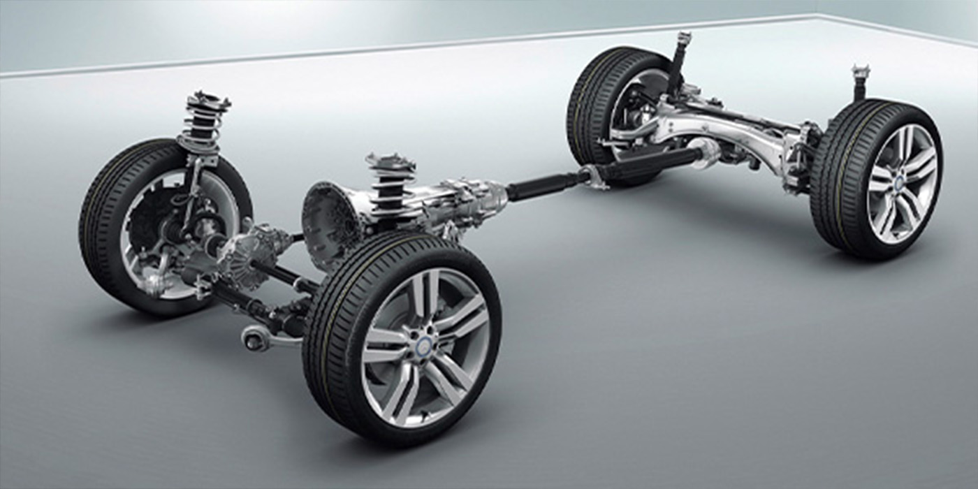
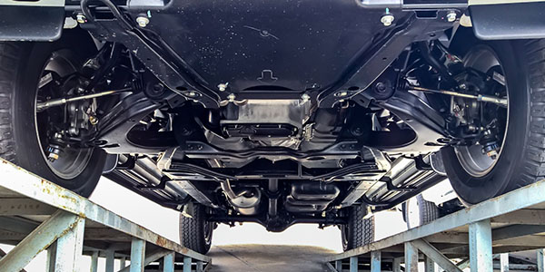
Ride Height
Ride height is more than a measurement to gauge the health of the springs. It is a diagnostic measurement that can be used even if you do not have the specifications or procedures. The best method to measure ride height is to measure the height of the lower inboard control arm bolt and the height of the spindle or center of the wheel. Subtract the height of the spindle from bolt height. Now, compare that measurement to the other side. If the measurement is 1/2” or more off from the other side, start looking for bent parts or worn bushings. After that, look at the springs for missing coils or just lackluster ride control qualities on the test drive.
The most important thing to remember is that as the suspension compresses, the alignment angles change. It is possible to set toe, caster and camber within specifications on a vehicle with lower ride height. But, as the vehicle travels down the road and the driver loads the vehicle with weight or cornering force the rate of change of the angles can increase and give settings that can cause a pull/lead condition.
Tires
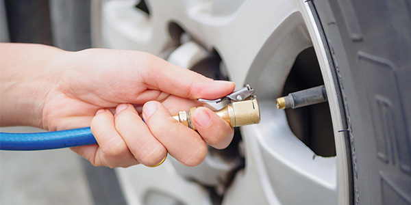
Tires can cause a vehicle to pull. While it is not as big of a problem as 20 years ago, it can still happen. Today’s tires are made to higher tolerances and the decreased sidewall area can reduce the chances of a tire’s rolling circumference from causing pulls. But there is one thing that remains constant, drivers not checking the inflation pressure regularly. A side-to-side difference as small as 3 PSI, can cause a lead/pull condition.
Rotating tires can give you an indication if the problem is related to the tires. If you can rotate the front tires side to side and the pull is in the opposite direction, you may have found your problem. If you rotate the tires front to rear and the problem is gone, you just might have solved the problem until the next rotation. Some balances are able to measure the “road force” of the wheel and tire assemblies. Look at the full set of tires and wheels and come up with a mounting strategy to cure the steering lead/pull.
Setback
Setback is a diagnostic angle that measures the difference in distances between the centers of the front or rear wheels, some higher end alignment systems can measure this distance. Differences in the setback side-to-side indicate damage in the frame or within components like control arms and bushings. Take a closer look at caster angles from side to side to see if there is a more significant problem.
In The Green, Still A Pull?
Even if all of the angles are in the green, the car may still have an alignment problem. Interpreting the angles and thinking about how an angle on one side can “add up” to trouble on the opposite side is critical for avoiding comebacks. Positive camber on one side with negative camber on the other can add up to a pull even if the specs are within tolerances because ±5° on both sides can add up to 10º.

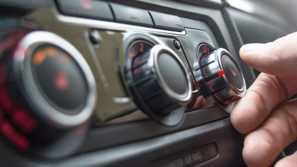
Steering Angles
Since 2012, almost every vehicle sold has stability control. This means there is a steering angle sensor behind the steering wheel. This can be a very helpful tool on a test drive to measure steering pulls. Typically, three degrees of steering angle is normal when traveling in a straight line. But, if you see larger values from the wheel speed sensor it could indicate a problem with the sensor.
If the error in the steering angle is large enough, it will disable the system and turn the system’s malfunction indicator light on to alert the driver. If the error is small, it will operate as normal until certain conditions like those seen when driving on freeway ramps and tight streets occur. Under these conditions, the computer might unnecessarily activate the stability control system, slowing the vehicle, or it may fail to respond with the right corrective action, causing it to leave the road.
Article courtesy Brake & Front End.