 Variable valve timing (VVT) is a way to advance/retard valve timing, and change duration, overlap and even lift in some applications while the engine is running.
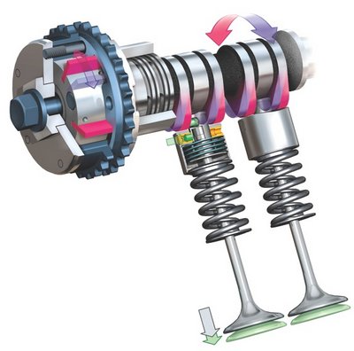
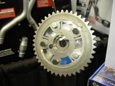
VVT is computer-controlled and typically uses oil pressure to change the position of a phaser mechanism on the end of the camshaft to advance or retard cam timing.
VVT has been used on numerous Japanese (Honda, Nissan and Toyota) and European (Audi, BMW, Mercedes and VW) engines since the late 1980s and early 1990s, but only in the last decade or so on domestic engines (such as Ford 4.6L V8s, Chrysler 2.4L and 3.6L VVT engines, Chevy 2.4L Ecotec, etc.).
On overhead cam engines where there are separate cams for the intake and exhaust valves, changing the timing of one cam also changes the effective duration and overlap, and on engines where VVT also involves activating extra cam lobes or changing the rocker arm fulcrum point, VVT can also change total valve lift.
It can even change an engine’s effective compression ratio by altering the opening and closing points of the intake valves during the intake and compression strokes. If that weren’t enough, VVT can also reduce pumping losses at idle for increased engine efficiency and fuel economy.
Think of VVT as the valvetrain equivalent of the powertrain control module (PCM) advancing/retarding spark timing and readjusting the air/fuel mixture as engine load and speed change to optimize performance, fuel economy and emissions.
The main advantage of VVT is that all of the factors traditionally associated with a given cam grind are no longer fixed, but can change in response to changing engine speed and operating conditions.
BMW has even figured out a way to eliminate the need for a throttle by using VVT and direct injection to control idle speed and acceleration. The BMW Valvetronic system uses a stepper motor and secondary eccentric shaft to actuate a series of intermediate rocker arms.
By varying valve lift and duration, the engine can breathe freely like a diesel with minimal pumping losses at idle and low rpm. This boosts fuel economy about 10% while also lowering emissions. At higher engine speeds, valve lift and duration are increased to add more power.
Camshaft Theory 101
Prior to VVT, camshaft timing, lift, duration and overlap were all fixed values and were determined by the location and shape of the lobes on the camshaft when the cam was ground. What’s more, the profiles and locations of the lobes were ground to optimize power within a certain rpm range.
Street engines spend most of their time from idle to about 3,500 rpm with occasional bursts to 5,500 rpm, so street cams are typically ground with less duration and overlap to increase low end torque. A cam with minimal duration and overlap also creates lots of intake vacuum, which allows for good throttle response, but it also creates pumping losses as the pistons struggle to pull air past the nearly closed throttle plates.
A good mid-range cam (2,500 to 4,500 rpm) gives up some low-speed torque and peak high-speed horsepower to obtain a fatter power curve in the middle rpm ranges. By comparison, a performance cam in a circle track car, drag car or even a street/strip machine is usually ground to deliver peak power at a higher rpm range.
Many racing cams actually produce less torque at low rpms than a stock cam and don’t start to make serious power until 4,500 rpm or higher! That’s why cam selection is such an important factor when building an engine.
Because of these factors, most cams (including performance cams) are still a compromise at best. The breathing characteristics of any camshaft works best within a fairly narrow rpm range, and everything on either side of that range is less than optimal.
Racers know this and try to choose a cam grind that will deliver the most usable power within the rpm range where they need it most – which for a dirt track engine might be from 4,500 to 6,500 rpm, or 5,500 to 8,500 rpm for a drag engine. Some racers use a data recorder to plot their engine rpms as they run laps around a track. Based on this information, they can then choose a cam grind that delivers the most usable power within the rpm range where they can really use it. The cam may not make the most peak power, but it will deliver the power where it does the most good – and that’s what it takes to win races.
On a street application, a cam has to match the gearing of the drivetrain, the weight of the car, the stall speed of the transmission (if it is an automatic), the rpm capabilities of the engine (valve spring and pushrod stiffness), the flow characteristics of the cylinder heads, valves, intake manifold and carburetor or throttle body, and the engine’s compression ratio. Get any of these wrong, and the cam will be a mismatch for the application and deliver less than optimal performance.
Changing Valve Dynamics
With a conventional camshaft, all of the variables that determine valve timing, lift, duration and overlap are cast in stone the moment the lobes are ground.
If you want to play around with valve timing to move the engine’s power band up or down a few hundred rpm, you can reposition the timing gear on the cam (or use offset bushings or pins) to advance or retard cam timing maybe 2 to 8 degrees either way.
Even then, the setting is locked in position and will not change once the bolts are tightened down. If you want more lift, you can install higher lift rocker arms, otherwise you have to change the cam to one that has taller lobes. But if you want to change valve duration or overlap, your only option is to swap the cam for a different grind.
With variable valve timing, none of these things are fixed. Valve timing, duration, overlap and even lift can all be changed electronically and/or hydraulically to alter valvetrain dynamics at any speed or to any change in operating conditions. This means VVT can increase valve duration, overlap and even lift (depending on the application) at higher engine speeds to increase peak power as well as broaden the engine’s torque curve across a much wider rpm range.
VVT can also be used to change valve overlap to reduce oxide of nitrogen (NOx) emissions when the engine is under load. Increasing valve overlap has the same effect as increasing exhaust gas recirculation (EGR) flow to suppress peak combustion temperatures. On some engines, VVT can eliminate the need for an EGR valve while improving idle quality and stability.
Inner Workings
A typical example of how VVT works would be the “Continuous Variable Valve Timing Control” (CVTC) system that Nissan uses on a number of its engines. On these applications, a hydraulic phaser is mounted on the end of each intake cam to alter intake valve timing with respect to exhaust valve timing. At low and mid-range speeds, intake valve timing is advanced 20 degrees to improve low-speed torque and idle.
This also changes the amount of intake/exhaust overlap from 8 degrees to 28 degrees. The phaser is actuated by oil pressure, which in turn is regulated by a computer-controlled solenoid.
When the solenoid is energized, the valve traps oil pressure inside the phaser cavity and prevents it from escaping. As oil pressure builds, it pushes the sliding cam drive or rotor inside the phaser. This rotates the cam’s position to advance timing. De-energizing the solenoid allows oil pressure to bleed out of the phaser oil cavity and the cam returns to its original position.
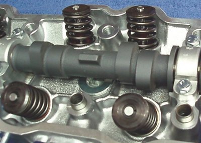
On Honda engines that have the “Variable Valve Timing and Electronic Lift Control” (VTEC) system, a different approach is used.
On these engines, the intake and exhaust valves are opened by individual rocker arms (followers) that ride under a pair of overhead cams (one intake, one exhaust).
Between each pair of rocker arms is a third rocker that rides against an extra cam lobe for each cylinder. The lobe has a typical performance grind with additional lift and duration for high-speed power.
At low rpm, the third rocker is just along for the ride and does nothing. The two rocker arms on either side follow their respective cam lobes to provide relatively mild valve lift and duration for good low-speed torque and throttle response.
When engine speed increases, however, the PCM energizes a solenoid that allows oil pressure to flow into the hollow pivot shafts that link the extra third rockers with their companions. Oil pressure shoves pistons inside the pivot shaft sideways to lock all three rockers together. This causes the intake and exhaust valve rockers to be pulled away from their normal lobes and to follow the profile of the third rocker lobes.
It’s like shifting from a standard grind cam to a race grind – which changes lift as well as duration and overlap. Return springs in the rocker pivot shafts retract the pistons when oil pressure is relieved, disengaging the third rockers and allowing the intake and exhaust rockers to return to their normal lobes.
Back in 2008, Toyota introduced its “Valvematic” VVT system. It uses an electronic actuator mounted on the end of the intake rocker shaft. The shaft rotates to change the lift ratio of the rockers.
The system can vary valve lift from 1.1 to 11.5mm compared to a static valve lift of 9.9mm for a similar engine without the Valvematic system. Valve duration is also variable from 106 to 280 degrees compared to a static 246 degrees for a non-Valvematic engine. Toyota says this system is good for a 10% gain in both horsepower and fuel economy. You’ll find it on the 2014 Corolla 1.8L engine.
Today’s VVT Applications
On performance applications, VVT can provide the best of both worlds: good low-end and mid-range torque, fuel economy and increased high rpm power.
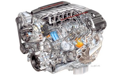
In the 2014 Corvette, the LT1 engine (shown on page 36) is a pushrod engine like its LS predecessors, but it has a cam phaser mounted on the front of the cam that can advance/ retard cam timing up to 62 degrees! The LT1 cam is a conventional one-piece design so only valve timing changes when the phaser is doing its thing. Valve duration, overlap and lift all remain the same.
GM also uses cylinder deactivation on this engine (spark and fuel injectors) to improve fuel economy, but the valves continue to operate on the dead cylinders.
Although the cam phaser in the Corvette LT1 engine provides a lot of latitude in cam timing, it can also create tuning and valve-to-piston clearance problems if the engine is being modified for a racing application. The answer is to install a cam phaser limiter kit in the phaser that either locks the phaser in a fixed position (thus eliminating VVT altogether) or limits its travel to no more than 15 to 20 degrees. This, of course, requires reprogramming the PCM so it won’t try to change cam timing or to advance or retard it more than the new limit.
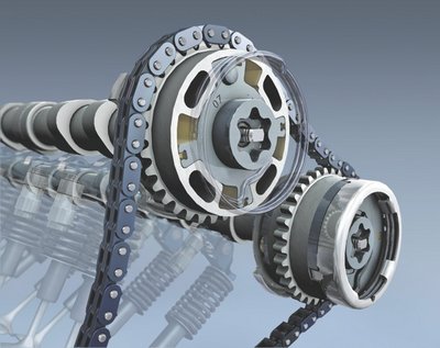
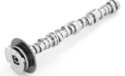
On newer Dodge Vipers, VVT is also used with their V10 pushrod engine. On these applications, a special “concentric” camshaft within a camshaft is used that allows valve timing, duration and overlap to change.
The concentric cam has a solid inner core and an outer tube assembly. There are two sets of lobes, one set fixed to the outer tube and a second set pinned to the inner shaft through slots in the outer tube. The phaser on the end of the cam rotates the position of the inner shaft with respect to the outer tube to change valve timing, lift and overlap.
The 2014 Mazda 6 with its 2.5L Skyactiv engine has an unusually high static compression ratio of 13:1 (close to that of a diesel), but it can burn regular unleaded 87 octane gasoline thanks to VVT. By carefully adjusting valve timing and overlap, as well as the timing of the direct gasoline injection system, this engine can run extremely lean and deliver up to 15% better fuel economy than a conventional engine with fixed valve timing and a normal compression ratio of around 9.5:1. The VVT system on this engine holds the intake valves open longer after the pistons pass bottom dead center (BDC) on their intake stroke. By increasing intake valve duration past BDC, some of the air in the cylinder is actually pushed back out (reverse flow) to reduce the engine’s effective compression ratio at idle and low speed.
VVT Vulnerabilities
As great as VVT is, it is also vulnerable to some problems. Oil quality, viscosity and contamination problems can all affect the operation of a hydraulically actuated VVT cam phaser.
If the phaser isn’t getting adequate oil pressure, or the oil is the wrong viscosity (too thick or too thin), or the oil is dirty, it may prevent the phaser from working properly.
This, in turn, will affect engine performance, fuel economy and emissions, and will often turn on the Check Engine light and set a VVT-related fault code.
Ford has experienced some cam phaser issues on high-mileage 4.6L V8 engines. The problem in this case is not the phaser itself, but a lack of sufficient oil pressure to the phaser. The overhead cams on these engines do not have bushings, but run in bores in the aluminum cylinder head.
As wear adds up over time, cam journal to bore clearances increase causing a drop in upper valvetrain oil pressure.
This, in turn, may prevent the phaser from getting enough oil pressure to advance the cam normally. The result can be engine noise and/or a VVT-related fault code. One fix is to remove the cylinder head, machine out the cam bores and install aftermarket bushings to restore normal oil clearances – or to replace the head altogether.
Both of these are expensive fixes, so another alternative is to install a cam phaser “repair kit” that essentially locks the phaser in a fixed position.
The kit includes a pair of metal plugs that are installed inside each phaser to prevent any phaser movement.
Similar kits are also available for engine tuners who want to limit or reduce the maximum amount of phaser travel on these engines (as when installing a hotter cam or higher compression pistons). Similar phaser limiter kits are also being developed for the 2014 Corvette LT1 engine.