A resistance spot weld is the joining of overlapping pieces of metal, achieved by applying pressure and electrical current. In other words, a spot weld is formed when a large amount of current (ampere) is passed through copper — electrodes that are held in place by pressure exerted on them.
 As the electricity flows through copper and comes in contact with metal that’s being welded, a resistance is formed in the electrical path and heat is generated. As the heat builds up, the metal (in contact with the tips of the electrodes) melts.
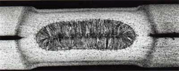
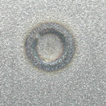
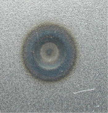
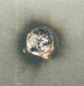
The pressure that’s exerted on the weld site (electrodes are forced together by creating a pressure on the tips) causes the metal to deform, producing a “weld nugget” or a small circular dent as it cools. See Photo A.
When welding using STRSW machines, you need to consider a number of variables:
• Pressure — Pressure is needed at the weld site to force the molten metal together and keep pressure on the nugget until it cools. Too much pressure at the tips will decrease the resistance factor. Too little pressure will cause weak, small weld nuggets.
• Weld time — Too long of a weld time could lead to the base metal exceeding its melting point or even its boiling point. These conditions could lead to gas porosity or even exploding welds. Too short of a weld time won’t allow enough amps to flow to form a proper weld.
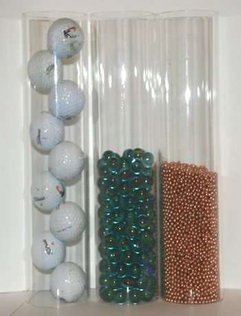 To make things a little simpler to understand, I took plastic cylinders and filled them with golf balls, marbles and BBs. See Photo B.
The golf balls represent the molecules in mild steel, marbles high- strength steel and BBs advanced steel. If the cylinders were filled with water, all the voids between the objects would be filled. If the cylinders with the BBs and marbles were frozen, both containers would be a lot stronger.
Now if the cylinders are warmed, a slight melting would occur. You’d get a weakening of the structure. Add a lot more high heat, the water melts, and both the marbles and the BBs would lose the H2O binding between the molecules. (And this is a one-way process; we can’t refreeze the water in this scenario.)
I know this is a simplified demo, but it’s a good representation of what heat does to the new metal. Heat applied to advanced steel with boron reduces its original strength by up to 75%.
• Current (amps) — This is the flow of electricity through a conductor. Heat is generated in STRSW by adding more amps. Too much heat applied to the weld nugget, and the surrounding metal becomes brittle and loses weld strength — and the weld can even explode. Too little heat will cause a weak weld.
• The type of metal being welded — When life was simple, we only had to worry about 18- to 22-gauge metal on a car. With the introduction of ultra high-strength steels, things are starting to get complicated. Today we’re dealing with trip steel, dual-phase steels, laser-welded tailor-made banks, advanced steels and advanced steels with boron. We’re challenged as an industry to deal with these new metals.
One particular challenge: The effect of welding heat on these metals can have dramatic effects.
So how do we know what’s the correct amount of heat?
Inverter welders
Inverters take the incoming A/C volts and, through a series of devices, convert the voltage into high amp, low voltage (13 volts) DC current. With high amps and low voltage, a number of benefits can be derived.
First, direct current output is constant. A/C current goes through a cycle (50-60 cycles) per second. When welding thin metals, heat is generated above the zero line (positive) and cools below the zero line (negative). The thin metal will begin to fuse only after a couple of cycles and, if the metal cools significantly during the cycle, resistance is lost.
To overcome this loss of resistance, a longer weld time is required, which will produce more heat to the metal surrounding the weld nugget. By using DC current for the weld, there’s a constant and even supply of voltage.
There are also a number of other advantages, such as the ability to “fine tune” the voltage (amps).
Instead of using a range, the new machines, by using computers, can dial in precisely the best amp/volts to produce a proper weld on the new metals being used on today’s vehicles. Yes, you read it right — these new inverter/resistance spot welders are using computers.
That being said, let’s take a look at the electrical source that operates these machines.
While I was getting ready for our welding demonstration, I found out that all seven of the machines needed 220 volts of three-phase power. Three-phase power uses three frequency waves instead of one during one cycle.
When one wave is at zero, the other two are still delivering power. With all lines producing electricity, a constant voltage is achieved.
To use inverter technology, a constant voltage is needed, which is why the shop needs a 220-volt three-phase power source. Besides having three-phase power, you also need a way to deliver the correct electricity to the equipment.
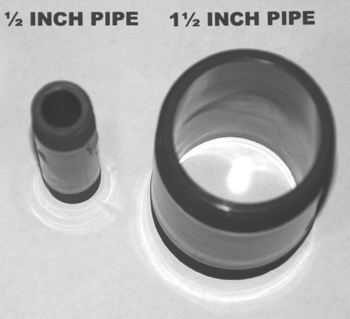 Let’s examine the required wiring: Remember that we need the proper current (amps) supply for the welder. Most of the inverter welders need between 50 and 65 amps service. What does that mean? Since trying to visualize electricity is nearly impossible, I’ll try to explain it in a way that makes it understandable. To start, check out the figure below of the 1/2-inch pipe and 2-inch pipe. See Photo C.
Think of water flowing through the pipes as current. If you can get by with the amount of water that the 1/2-inch pipe delivers in a set amount of time, you’re in good shape. But what if you need more water?
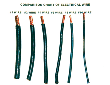 You’ll need a larger pipe. In electricity, electrical wire is pipe. The gauge of the wire is represented by the diameter of the pipe. See Photo D.
Most machines need a minimum of service (wire and size). And that equates to a #6 wire. A 65-amp service needs #4 wires. If the electrical run is longer (more than 80 feet), you should use the next size wire.
So, before you invest in an inverter spot welder, you should consult with an electrical engineer to determine if you have three-phase power and a proper electrical panel and if you’ll need to run additional conduit to handle the circuitry.
11 Rules for Making Good Spot Welds
1. Too short squeeze time can result in metal expulsion, overheating electrodes, bad welds and marked work.
2. Too long weld time will shorten electrodes life, cause excessive indentation at surfaces and cause internal cracks in the weld nugget.
3. A peel destructive test on test strips of the same material/combination is recommended.
4. Too short weld time will result in low weld strength, in proportion with weld heat.
5. Too short hold time can result in surface expulsion, electrodes sticking and internal cracks in the weld nugget.
6. Weld pressure too low can result in expulsion of metal, electrode sticking, short electrode life and internal cracks in the weld nugget.
7. Weld pressure too high can result in variable weld strength, excessive weld current requirements, mushrooming of electrodes and excessive indentation.
8. With all other settings correct, adjust weld current to meet weld quality standards using recommended starting points.
9. Electrode contact face too small will result in too small a spot, excessive electrode mushrooming and excessive indentation. Too large an electrode contact area will result in too large a weld (assuming current is set accordingly). Use RWMA charts for electrode manufacturer recommendations.
10. Misaligned or mismatched electrodes will result in expulsion, displaced weld nugget and excessive electrode wear.
11. Insufficient cooling will result in mushrooming and short electrode life. Adequate water cooling of the welding system is crucial.
 How to Prevent Exploding Welds
 1. Panel Prep: All sides of replacement panels must be buffed with all e-coat being removed (no factory
 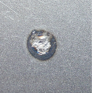 primer). Caution: Do not remove galvanized coatings.
 2. Weld Primer: If weld primer is to be applied, complete the welding process while the primer is fresh, preferably within the first hour and not longer than eight hours. (Cured weld primer is the same as the factory coating and will often restrict continuity.)
3. Recommended Tip Type: Utilize a dome-shaped tip; the tip should be flattened 5 mm at the top of the dome.
4. Squeeze Pressure: With most guns/pliers, adjust squeeze pressure to the maximum amount possible. Multi-panel compression welding requires very high gun squeeze pressure — in most repair situations, 500 to 900 pounds at the contact tips. Super and ultra high-strength steel multi-layer panels may require pressures in excess of 900 pounds.
5. Contact Tip Gap: Check to see if the gaps between tips are correct. The type of squeeze gun and manufacturer’s recommendations will determine gap distance.
6. Arm Angle: A bad arm or contact tip angle may cause welds to explode; arms should be square to the area being welded.
7. Weld Sequence: Start at one end and move in one direction. Do not jump around.
8. Host Panel E-Coat: In areas between the host panels, where it’s visually evident that there’s excessive factory coating between the host panels, hammer and dolly the affected area prior to clamping on the replacement panel to break up the excessive coating between the host panels.
9. Questionable Areas: On areas without a good flush fit, attach vice grips on both sides of spot to be welded.
10. Follow Your Weld: At each weld spot, place a vice grip as close as possible next to the weld spot; this will increase the quality of the weld, while supplementing the squeeze performance of the gun pliers.
These four photos courtesy of Elektron
For more articles and training documents on welding, enter welding in the content search function on the T2 homepage.