With local shops booked weeks in advance this summer, I found myself going back to school to understand how brake controllers are wired to the factory harnesses and what the pin functions are for all seven wires of a heavy-duty trailer connector.
This month’s Diagnostic Dilemma begins with two case studies in ascending order of difficulty: 1) several ABS warning lights coupled with no electric brakes on a fifth-wheel horse trailer, and 2) the park light circuit activating the brakes on a brand-new camping trailer. While both of these problems appear simple on the surface, the addition of anti-lock braking systems (ABS) and changing electrical architecture makes them a little more challenging than we might suspect.
THE HORSE SAYS: The owner of a 1999 Dodge 2500 Ram pickup called me mid-summer with an ABS and check engine warning light problem on his instrument panel and no trailer brakes on his fifth-wheel horse trailer. Excluding the electronic aftermarket brake controller, this Dodge had a “hardwired” trailer lighting and braking system with no intervening modules. The owner had attempted to fix the trailer brake himself by twice replacing the trailer brake controller. With 245,000 miles on the odometer, this Ram 2500 typifies what we’re seeing as the age of our national fleet approaches 12 years and older in some areas.

CODE RED: This truck had a multitude of problems — many of them caused by human hands. Beginning with a scan tool analysis, the check engine light represented a code P0336, which the scan tool database described as a “CKP signal error.” Several ABS codes were also present, which illuminated both the orange and red brake warning lights. The scan tool displayed “active” codes 65 (internal main relay open), 52 (rear dump solenoid open), 51 (rear isolation solenoid open), 42 (right front dump solenoid open) and 46 (left front dump solenoid open). Going to the “stored” codes, I found only code 65 indicating that the internal main relay built into the ABS module had failed to close the circuit. Also among the stored codes were code 81 (brake switch circuit) and code 74 (system control mode timeout). Before getting into the trailer brakes, it’s time to separate the wheat from the chaff on trouble codes.
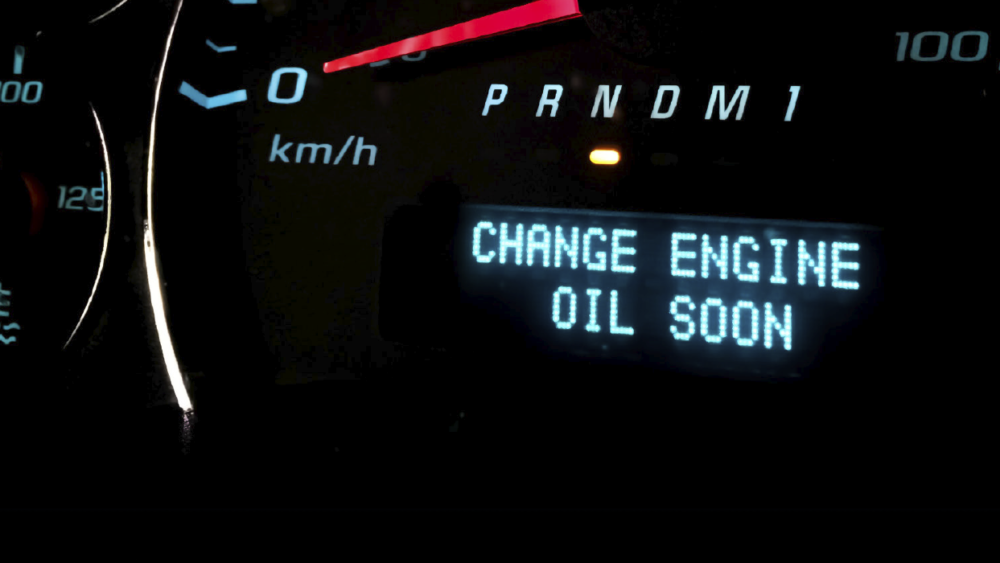
CODE P0336: P0336 sets when the signal voltage is below normal. According to service information, the only effect of a CKP failure is reduced turbocharger pressure and engine power. No engine performance problems had been experienced, so we deferred repairs on P0336.
CODE 65: According to the scan tool code summary, code 65 sets when “all solenoid feedback voltages are low when they are expected to be high,” and when there is high voltage when the solenoids aren’t energized. Causes include low ignition switch voltage, bad ground circuits and an internal CAB failure. I decided to look at the CAB power and ground circuits after I repaired the trailer brake circuit.
CODES 52 THROUGH 81: Regarding the multitude of ABS-related codes, my plan was to clear the ABS diagnostic memory and drive the vehicle at speeds above 40 mph to see if any of these codes reset. A laundry list of trouble codes stored in the CAB module can be indicative of a voltage drop on the CAB’s power and ground circuits. On the other hand, Code 81 (brake switch circuit) might have been set when the brake controller was installed. I also had to remember that the customer’s repair priority was the trailer brake failure, not the check engine and ABS warning light issues.
HOW IT WORKS: Wiring schematics indicated that a light-blue wire energizes the trailer brake. The trailer light diagnostic tool’s LED test lights indicated that all circuits were active except the trailer brake. After removing the aftermarket brake controller from the dash bolster panel, I repaired several open circuits caused by poorly crimped butt connectors.
The Internet proved helpful because the brake controller manufacturer posted its wiring diagrams on its website. The standard color codes supplied by the manufacturer for its four-wire brake controllers are: blue (trailer brakes), black (battery positive), red (stoplight switch or brake sense), and white (ground). These color codes go awry once they enter the OE harness, and for that reason, I ignored them.
The standard trailer connector outlet color codes are: pin 1 = chassis ground (white), pin 2 = electric brakes (blue), pin 3 = tail or marker lights (brown), pin 4 = trailer batteries B+ (black), pin 5 = left turn/brake (yellow) and pin 6 = right turn/brake (green). Orange connects to the auxiliary center pin for backup lights. I verified a brake switch signal on my scan tool and at the controller as the brake pedal was depressed. I also verified that the controller was switching B+ voltage to the light-blue wire in the OE harness leading to the rear trailer brake connector. I then followed the light-blue trailer brake wire through a connector under the left front fender, through the OE harness and to three trailer outlets: one inside the bed, one on the trailer hitch and another small round outlet on the underside of the bed. Next, I stripped the harness to see how all of this wiring was connected.
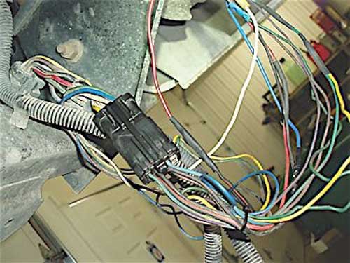
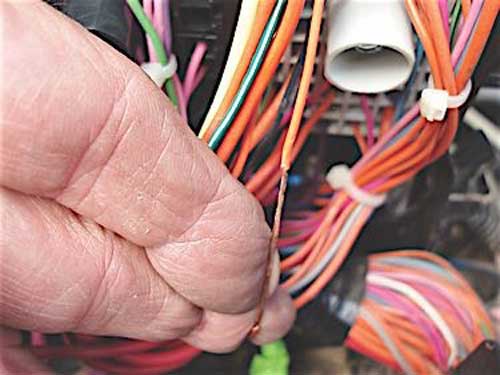
A WIRING MAZE: Typical of amateur wiring projects, many potential failure points were introduced into the wiring harness by using crimp connectors to splice short lengths of different colored wire together. I found the light-blue trailer brake wire broken inside the original equipment (OE) split-loom harness fastened to the driver’s side frame rail. I speculated that this wire either had a manufacturing defect or had been damaged by mechanical strain. At any rate, redoing the wiring maze under the rear bumper and soldering a new length of wire onto the light-blue trailer brake wire resulted in full voltage and amperage flowing to the trailer brakes.

To address the ABS codes, I cleaned the G100 ground at the left front fender and checked voltage and continuity on the 40-amp cartridge fuses #8 and #11 in the underhood fuse box, as well as the 10-amp mini fuse #3 in the interior fuse box. While a test drive over 40 mph didn’t reset any of the previously recorded codes, code 65 did return a few days later. Due to the randomness of code 65, and considering that the CAB controller wasn’t likely available for a 17-year-old truck, I suggested testing for voltage drops through the ignition switch. Due to the other issues, the owner declined the diagnosis.
THE TRAILER BRAKES APPLY WHEN: A retired couple had just bought a brand-new camper trailer to tow behind their well-maintained 2003 Chevrolet Tahoe when they discovered that the trailer brakes were applied when the park lights were turned on. According to the husband, local repair shops didn’t have a clue what the problem was. The mechanic at the RV dealership tested the trailer connector outlet and correctly determined that the Tahoe’s park light circuit was somehow “bleeding” into the trailer brake circuit. That said, the most common point for the exterior lighting to “bleed” into the brake light circuit is through a defective dual-filament rear tail light bulb. I replaced both bulbs, but with no success.
Like the Dodge owner, the Tahoe owner took it upon himself to twice replace the brake controller before our local parts store referred him to me. Following standard practice, I verified the complaint with the customer. Sure enough, the trailer brakes applied when the park lights were turned on. A scan tool analysis didn’t yield a clue except that the brake switch was activating as it should. And therein begins our tale of a brake light switch that isn’t hardwired to the brake controller.
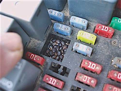
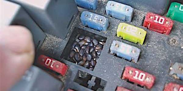
THE RODENT HOTEL: Inserting a trailer circuit tester into the Tahoe’s OE trailer connector, I confirmed that 1) the trailer brakes weren’t activating at all with the lights turned off, and 2) no chassis power was being supplied to the trailer batteries. Because the brake controller plugged into a standard OE towing package outlet, and since the Tahoe’s trailer connectors were OE as well, tampering issues appeared to be eliminated. My conclusion at that point was that the trailer wiring harness had somehow become damaged by rodents and that the best place to begin on an early 2000s Chevrolet truck was the fuse box. My suspicions were confirmed when I found the fuses and relays coated with dried rodent urine and droppings.
HANTAVIRUS ISSUES: In brief, Hantavirus disease is contracted by breathing dust from dried urine and feces contained in the nesting materials of the deer mouse, cotton rat, rice rat and white-footed mouse — each of which lives in various areas of the continental United States. Hantavirus usually hospitalizes a person and can be fatal, even with the best medical care. For this reason, never use compressed air to remove rodent nesting materials, especially in a closed space. For a more comprehensive coverage of Hantavirus symptoms and prevention, look up “Hantavirus” on an Internet search engine.
FINDING A FIX: After washing out the fuse box with warm water, soap and disinfectant, and drying it with low-pressure compressed air, I found only one wire stripped of its insulation. Due to limited accessibility, I coated it with an aerosol anti-corrosion compound and reinsulated it with four inches of spiral wrap. After reassembling the fuse box, I measured 11.83 volts on the battery post and 12.80 volts on post #1, which indicated that post #1 was connected to the trailer batteries. My schematics indicated a 40-amp cartridge fuse should have been located adjacent to post #1, but I instead found a silicone rubber plug. After replacing the plug with the indicated 40-amp cartridge fuse, I had chassis power to the trailer batteries. Other than that, the rodent damage at the fuse box turned out to be another diagnostic rabbit hole.
During testing, I also discovered a significant voltage drop at the trailer connector ground pin. Chevrolet grounds the vehicle and trailer lighting through ground G401 located at the left rear body mount. Since G401 would ground the tail lights but not ground a 5-amp current flowing through an old headlamp, I cleaned and coated it with an anti-corrosion aerosol.
As for the trailer brakes, the schematic indicated that a white wire from the stoplight switch was connected to a “turn signal/flasher module” located under the dash. The turn signal/flasher module turned out to be a diagnostic game changer. While the white wire leading from the stoplight switch showed brake sense voltage, it wasn’t being received at the brake controller’s red wire. But, when park lights were turned on, B+ was supplied to the brake controller red wire, which the controller interpreted as a brake sense signal. This was the reason the trailer brakes were being applied when the park lights were turned on.
In the meantime, the owner had called the service manager of the Chevrolet dealership where he had purchased his 2003 Tahoe. The service manager indicated that the OE towing package on the 2003 Tahoe does indeed have wiring problems. Armed with that information and my own analysis, I concluded that the Tahoe had a wiring error inside the main wiring harness. While I don’t like altering OE wiring, the obvious fix was to solder the red brake sense wire from the brake controller to the white brake sense wire from the stoplight switch. With that repair completed, the brakes and exterior lighting on the Tahoe and its new RV camper worked perfectly, and the old retired couple were on their way to a great weekend of camping and fishing.