 Although it’s hard to believe that nearly 20 years have passed since the last carburetor was installed on a mass-produced vehicle, carburetors are still the fuel system of choice for many off-road, street performance and track racing enthusiasts.
In response to the performance market, aftermarket fuel system companies are now selling newly-designed carburetors, updated versions of old carburetors, remanufactured carburetors, new OE replacement “muscle car” carburetors and custom-built racing carburetors that will fit the requirements of any performance application.
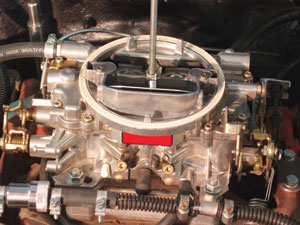
To help you understand how to optimize the performance of carburetors used in performance applications, we’ll cover the basic operating principles and adjustment procedures for several popular aftermarket and original equipment lines of carburetors including Edelbrock, Holley, Rochester and Motorcraft. Because of its simplicity and ease of repair, I’ll begin by using an Edelbrock model #1407, 750 cfm, non-emission four-barrel carburetor to illustrate the basic principles of carburetor operation and adjustment. See Photo 1.
The Carburetor Venturi
A venturi is a short, rounded, hour glass-shaped tube designed to draw fuel from the carburetor float bowl into the air stream flowing through the carburetor. The air passing through the tube at its narrowest point accelerates in speed and creates a negative pressure differential between the fuel in the carburetor float bowl and the air in the venturi.
Atmospheric air pressure in the float bowl then pushes fuel through the main metering jet into the negative air pressure in the venturi. Greater fuel metering accuracy and mixing capability is achieved by mounting a “booster” venturi inside the carburetor’s main venturi.
If the main venturi is too large for a particular engine application, the air pressure differential in the venturi will not be sufficient to draw fuel from the carburetor float bowl. The result will be a fuel metering “stumble” caused by inadequate air speed through the carburetor venturi.
To maintain a constant depression (vacuum) in the intake manifold as the secondary throttle plates open, several Edelbrock and Carter series carburetors may incorporate a set of weighted auxiliary throttle plates or spring-loaded air valves in the secondary throttle bores to maintain a slight pressure differential in the intake manifold as the engine accelerates.
Intake Manifold Vacuum
The term “intake manifold vacuum” describes the air pressure differential existing in the intake manifold when an engine draws air around a partially closed throttle plate. This air pressure differential is reduced as the throttle plate opens to allow more air volume to fill the manifold.
At wide-open throttle (WOT), the pressure differential is nearly equalized, but due to the inherent restriction of the carburetor main venturi and booster venturi, the air pressure inside the intake manifold remains slightly less than atmospheric pressure.
The Float System
The carburetor float, float needle valve and needle valve seat assembly maintain the correct fuel level in the fuel bowl. A low float level will cause a mild lean condition while a high float level will cause a mild rich condition due to the relative pressure differentials that the venturi must develop to lift the fuel out of the float bowl.
High and low fuel pump pressures influence the float level in the same way, with high fuel pump pressures tending to increase float levels and low fuel pump pressures decreasing float levels. In general, fuel pressures tend to range from 3 psi for small import engines to as much as 8 psi for full-bore drag race engines. Most carburetors perform very well with 5-6 psi of fuel pump pressure.
The Choke System
A choke plate mounted over the primary throttle bores is used to enrich air/fuel ratios for cold starting by restricting air flow into the carburetor. The choke system usually includes a thermostatic coil or hand cable to activate the choke valve, a fast-idle cam on the throttle plate to increase idle speed during engine warm-up, and a
vacuum-activated choke pull-off to open the choke valve a predetermined amount after the engine starts.
 The Six Metering Systems
Air flow through a carburetor venturi changes drastically as the engine accelerates from an idle to a wide-open throttle or peak engine-speed condition. To achieve a nearly “stoichiometric” or chemically perfect 14.7:1 air/fuel ratio, the carburetor must coordinate fuel flow with air flow.
To accomplish this, a typical carburetor uses six different metering systems to achieve stoich in the fuel delivery curve: the idle, transition (off-idle), accelerator pump, main metering, air bleed and power enrichment circuits.
Because the six circuits may overlap each other as the engine accelerates, the actual air/fuel ratio may vary throughout the speed and load range of the engine. In most cases, a carburetor must run slightly richer than “stoich” to avoid lean spots in its fuel delivery curve as it transitions from circuit to circuit.
The Idle, Transition and Accelerator Pump Circuits
The idle circuit consists of two tapered idle mixture adjustment screws that thread into small round ports located under the carburetor’s primary throttle plates. The primary idle circuit draws air and fuel into an emulsion tube, which mixes gasoline drawn through the carburetor’s primary main metering jet with air drawn from an air bleed 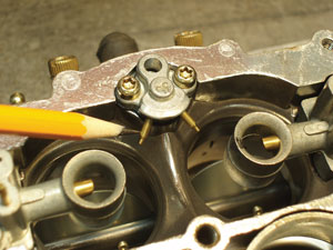 located in upper part of the primary carburetor body or booster venturi.
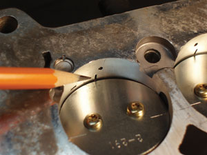
A transition “slot” circuit is located above the closed throttle plate. As the throttle plate continues to open, the transition slot adds fuel to the air rushing around the throttle plate. See Photo 2.
The transition slot draws its fuel from the idle circuit emulsion tube. As the throttle plate continues to open, fuel flow through the idle and transition circuits slows as the air pressure differential under the throttle plate decreases.
Keep in mind that, because liquid fuel flowing from the carburetor float bowl accelerates slower than the air flowing through the carburetor venturi, the carburetor will momentarily run lean until the venturi begins to draw fuel from the float bowl. To prevent the engine from developing a lean stumble during acceleration, an accelerator pump circuit is used to supply a short burst of fuel into the air flowing through the venturi. See Photo 3.
To achieve a relatively accurate fuel metering curve as the engine accelerates, the volume and duration of fuel 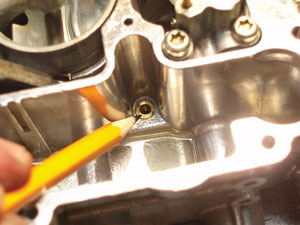 flowing through the accelerator pump nozzles are controlled by the mechanical length of the pump stroke, the spring pressure exerted on the pump piston, and the diameter of the accelerator pump nozzles located in the main venturi.
Main Metering and Air Bleed Systems
Creating close to a 14.7:1 stoichiometric or chemically correct air/fuel mixture ratio is a difficult assignment for a mechanically controlled carburetor. But carburetors come very close to creating “stoich” by employing a very sophisticated method of mixing air with fuel before the fuel enters the venturi air stream.
Fuel is drawn through the primary venturi’s main metering jet into a main metering emulsion tube. See Photo 4.
The emulsion tube is a part of the booster venturi and is inserted into a main metering well located in the body of the carburetor. Like the idle jet emulsion tube, the main metering emulsion tube draws air from a secondary air bleed and combines it with fuel drawn through the main metering jet. This “emulsifying” action prevents liquid fuel 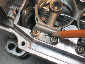 from being siphoned into the venturi air stream. See Photo 5.
Air bleeds perform the additional function of “curving” the air fuel mixture ratio so that the air fuel ratio remains relatively constant throughout the engine’s entire speed and load range. Without air bleeds to dilute the fuel stream with air, the carburetor would tend to run rich at peak engine speeds and loads.
Power Enrichment Systems
Internal combustion piston engines generally require rich air/fuel ratios only at wide-open throttle operating conditions. At part throttle, a carburetor delivers its best fuel economy at 15:1 and numerically higher lean air/fuel ratios. Keep in mind that, due to differences in air and fuel delivery to individual cylinders, we’re speaking of average, not absolute, air/fuel ratios when dealing with carburetors.
To vary the air/fuel mixture ratio, many carburetors like the Edelbrock 1407 restrict fuel flow during closed-throttle, high manifold-vacuum conditions by inserting a stepped metering rod into the primary main jet. Typically the 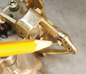 metering rod steps are of two diameters, such as the 0.071” and 0.047” diameters on our model #1407 Edelbrock carburetor.
A calibrated spring under the metering rod’s vacuum piston modulates the metering rod’s rate of descent into the main jet. At high manifold vacuum, the vacuum piston restricts fuel flow through the main jet by pulling the 0.071” portion of the metering rod into the jet. As the throttle plate opens and intake vacuum is reduced, the metering rod spring pushes the metering rod vacuum piston upward, allowing more fuel to flow around the 0.047” portion of the metering rod’s diameter.
Effects of Manifold Design
Carburetors deliver fuel in the form of small droplets suspended in a moving column of air. After the fuel leaves the booster venturi, the droplets tend to reunite in the form of larger droplets. These fuel droplets also tend to fall to the floor of an intake manifold plenum and to flow around the outside circumference of a curved intake manifold port.
This process of fuel segregating from the air inside the intake manifold is generally known as “wet flow.”
Designers of street performance manifolds attempt to reduce wet flow by applying exhaust heat to the underside 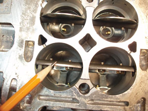 of the intake plenum. Although this added exhaust heat tends to evaporate liquid fuel by heating the plenum floor, it also reduces the volume of the air stream entering the engine’s cylinders. This segregation process is further aggravated by intake ports that are too large for the application and intake ports that have unnecessarily sharp curves in the port wall.
Consequently, it’s important to remember that manifold design controls not only the total air flow into the engine, but the cylinder-to-cylinder fuel distribution as well.
External Adjustments
Most specified thermostatic choke adjustments are accurate at sea level. As operating altitude increases, tension on the thermostatic choke spring must be reduced to accommodate reduced atmospheric pressure. Both the choke spring tension and fast idle speeds should be adjusted on a cold engine in order to produce the best cold-engine driveability.
The idle mixture adjustment consists of lightly seating the two spring-loaded screws located at the base of the carburetor. After seating, the idle mixture screws should initially be adjusted by backing them out two or three turns from their seated position. In general, a tachometer should be used to adjust idle mixtures.
 The idle speed screws should be adjusted equally until maximum idle speed is achieved. Keep in mind that, since performance carburetors can’t compensate for intake air temperature, a stoichiometric mixture in a hot shop environment will likely develop into a lean, rough idle condition in a cooler street environment.
A maximum idle speed adjustment will generally produce the best idle quality in a street environment. When adjusting idle mixture for minimum exhaust emissions, a slightly lean air/fuel mixture might be achieved by turning the idle mixture screws in to reduce engine speed by about 50 rpm. After the idle mixture is adjusted, the idle speed should be adjusted to specification. If the engine has a performance camshaft, the idle speed should be increased until an acceptable idle quality is achieved.
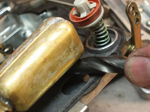
Most carburetor rebuild specifications indicate an accelerator pump height and linkage position adjustment. Lacking those specifications, adjust the accelerator pump by reducing pump stroke until a hesitation appears during acceleration. Increase pump stroke until the hesitation disappears. See Photo 6.
Last, always adjust the throttle linkage until the primary throttle plates achieve a wide-open, vertical position. After adjusting the throttle linkage, inspect the secondary throttle plates to ensure that they also reach a vertical position.
Keep in mind that partially opened throttle plates can cause poor cylinder-to-cylinder fuel distribution. Secondary throttle plate vertical position is adjusted at the secondary linkage. Most secondary plates also incorporate a throttle stop to ensure that the plates don’t rotate to an over-centered position. See Photo 7.
Internal Adjustments
Float level dimensions are adjusted by gradually bending the float arm until the float level reaches the
specified dimension. See Photo 8.
In most cases, the float should align parallel to the float bowl cover surface. Float drop is adjusted by bending a limiting tab located on the float arm. On the model 1407 Edelbrock carburetor, the float should drop nearly to the bottom of the float bowl.
Primary and secondary main jetting is very close on a new Edelbrock carburetor. In most cases, the only adjustment required is reducing the main jet size one or two steps to compensate for higher altitudes.


