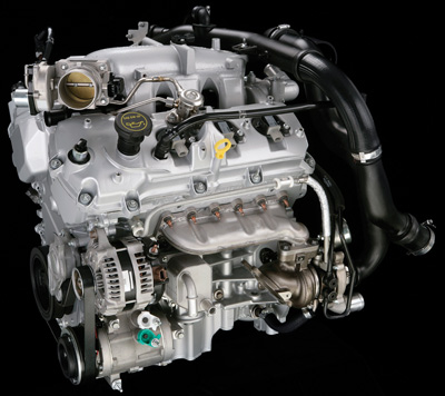
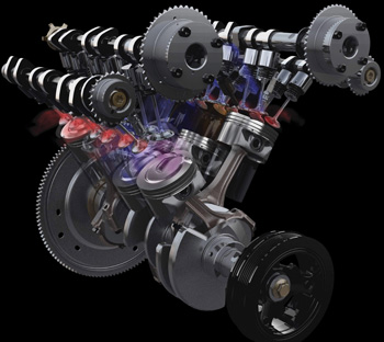
 The 3.5L EcoBoost is Ford’s first direct injection gasoline engine.
EcoBoost is part of Ford’s ongoing and wide-ranging initiative to deliver fuel-efficient powertrain systems with the type of power and performance usually only found in larger-displacement engines.
By 2013, more than 90% of Ford’s North American nameplates will be available with EcoBoost.
According to the company, Ford engineers used virtual tools and know-how to perfect the combustion system of the 3.5L EcoBoost V6 engine in order to handle a wider range of operating conditions and pressures, and still deliver V8 power coupled with V6 fuel economy.
You may hear the term GTDI (Gasoline Turbo Direct Injection) when referring to these engines.
Direct injection means that the fuel injector sprays fuel directly into the combustion chamber, rather than into the intake manifold or cylinder head ports.
It’s no secret that moving the injectors closer to the intake valves provide better efficiency and more even cylinder contribution, when comparing central fuel injection systems to port fuel injection systems.
 That was mainly due to a more even fuel distribution to each cylinder as well as better fuel atomization in each cylinder.
Now, with direct injection, a power and efficiency benefit is gained (approximately 15%) over port injection systems.
This gain largely comes from the fact that no fuel is lost on the hot intake manifold walls, as well as better atomization by several unique direct injection aspects, including shooting the fuel directly into the swirling turbulent air that is present under the intake valve as the air rushes into the cylinder.
As a driver of one of these little powerhouses, you’ll notice it feels like a V8. That’s because the GTDI 3.5L builds torque output to 350 ft.-lbs. at 2,000 rpm. The torque output stays flat-lined at 350 and doesn’t fall off until around 5,200 rpm. Horsepower builds to a peak of 355 hp at around 5,500 rpm.
With all that instant torque down low in the rpm band where the typical stop-and-go driving needs it, the fuel economy stays V6-like while the power feels V8-like — a strong V8 at that.
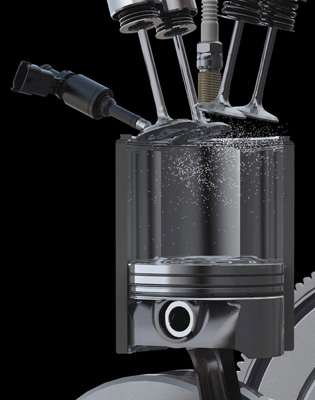
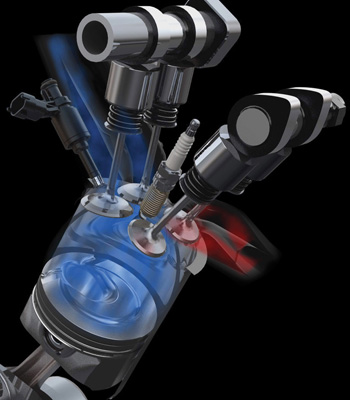
How it Works:
Fuel is injected directly into the combustion chamber through a high-pressure fuel rail (A). The system can deliver pressures up to 2,175 PSI, which is more than 35 times higher than conventional port fuel injection systems. As the fuel vaporizes and mixes with air, the charge is cooled, resulting in reduced knocking tendency (B). The denser charge created by the direct injection system results in greater power compared with a port fuel injection system. The spray pattern, which comes from six pinhole-like openings in the injector, is carefully calibrated to optimize fuel burn (C). The cleaner combustion results in faster starts and lower emissions. 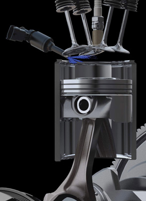
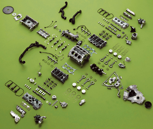
Base Engine
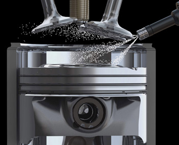
The pistons of the GTDI 3.5L are different than that of the standard 3.5L. Whereas the standard 3.5L has an overall flat top piston, the 3.5L has a dome top piston with a recession in it to increase atomization.
As the fuel sprays into the cylinder, it sprays into the recession helping the fuel to swirl and spread throughout the cylinder. Oil injector nozzles are aimed at the piston dome from the under side of the piston to help cool them.
This is one good reason why it is critical to use the specified 5w20 oil. Using too thick of an oil could reduce flow volume and velocity from the nozzles and cause piston damage.
The GTDI engine uses variable cam timing on the intake cams, same as the conventional 3.5L; again, another reason the proper oil type is used in these engines. Intake cam timing is advanced and retarded by pulsing a solenoid that fills and empties chambers inside the multi-piece intake cam sprockets.
This causes the camshaft to change clocking position in relation to the sprocket teeth up to 29°. Desired position is calculated by the PCM based largely on load percentage.
Actual cam positions are monitored by cam position sensors. Too thick of an oil can fail to pass through the tiny solenoid and oil manifold passages to fill and empty the sprocket (referred to as a cam phaser), at the proper rate.
 This could do anything from just setting a check engine light with variable cam position error codes (which is most likely), to causing a misfire and power loss (less likely, but possible, especially in a brief intermittent circumstance).
Intake and Fuel System
The fuel system on these engines has two sides: a low-pressure system and a high-pressure system. If you’ve worked with DI diesels, then the concept isn’t new to you. The low-pressure system is a mechanical returnless system consisting of an ordinary-looking electric fuel pump mounted inside the gas tank and a three-port fuel filter. Although it technically does have a “return,” via the third fuel filter port, it is still considered a returnless system. The low-pressure pump supplies 65 psi of fuel pressure through the lines leading to the high-pressure pump.
The driver module controls the pump’s speed by duty cycling the pump’s ground circuit. The low-side pressure system has a fuel pump driver module that is commanded by the PCM, similar to an electronic returnless system.
The low-side pump operation is unique. When the courtesy lights are activated, either via the remote key fob or door ajar switches, the power saver relay inside the smart junction box (non-serviceable relay) sends a “wake up” voltage to the PCM.
 When the PCM wakens, it turns the fuel pump relay on for two seconds, priming the low-side fuel system. This is done to remove any fuel vapor inside the lines at the high-pressure fuel pump. However, when the PCM receives a valid rpm signal, it actives the fuel pump driver module, which then turns on the fuel pump.
There is no low-side pressure sensor, yet the PCM does control the low-side pump speed via the control module. The low side has two speeds: low and high.
To achieve a low speed, the PCM sends a 37% duty cycle signal to the fuel pump driver module (FPDM), which in turn, operates the pump at around 60% capacity. If the PCM determines a need for higher fuel delivery, it can increase its duty cycle to 47%, which will raise the low-side pump’s operating capacity to 100%.
Low-side pressure must be tested using a conventional fuel pressure gauge. The early models have a test port on the accumulator. Later models will require a test adapter hose to be installed.
The pressure accumulator on the low-side lines is used to help prevent fuel vaporization. The low-side pressure system uses a more high-tech version of the old “inertia switch” that we’ve seen on Ford vehicles since the early ‘80s.
It uses what is called an “event notification system.” With this system, the restraints control module (RCM) will notify the PCM or the FPDM (depending on model) directly to shut down the pump if a crash is detected. Under normal operation, cycling the ignition will restore fuel pump operation from a collision detection shut-down.
 That is, when everything is performing as it is designed. That detail is important to remember because as repair techs, we usually only see them when something isn’t working as designed. So obviously the ability to scan the RCM, at least to look for collision detection codes, has become a part of diagnosing an inoperative electric fuel pump.
The high-pressure system consists of a high-pressure fuel pump that is mechanical and driven by a special four-point camshaft lobe that is only for pump operation. The plunger action of the high-pressure pump boosts fuel pressure up to 2,150 psi.
At these pressures, it is critical to exercise caution! High-pressure fuel can cut the skin, injecting fuel into the blood stream, which can be fatal.
The high-pressure fuel is in the metal line leaving the pump to the rails as well as the fuel rails. There is also no return line in the high-pressure system. The high-pressure pump mounts on the left valve cover. Pressure in the high-pressure system swings widely with rpm and demand.
Pressures here will swing from as low as 1,000 psi to 2,150 psi depending on conditions.
Pressure is controlled by balancing the volume through the pump and into the rail versus the volume passing through the injectors. One complete revolution of the camshaft produces four strokes of the high-pressure pump.
At maximum, these four strokes equal 1 cc of fuel delivered to the rail. If met with a dead end, that 1 cc of fuel would raise the rail pressure by about 800 psi. The injector cycling will vent that fuel into the cylinders at around 21 cc per second.
 The PCM raises and lowers the high-side fuel pressure by pulsing the fuel inlet valve (solenoid) on the side of the pump.
The inlet valve controls not only the amount of fuel that enters the pump chamber, but also the amount that bleeds back into the low-pressure system when the pump’s plunger pushes the fuel out.
The more the pump is filled, and the less that bleeds back into the low side, the higher the pressure will be in the rails. The PCM monitors a fuel rail pressure sensor to determine the needed action at the volume regulator. The pressure sensor is mounted to the top of the left-hand rail.
The gasoline DI injector is unique. The injector is opened purely by electrical pulse width like a conventional gas engine injector.
The GTDI injectors mount underneath the lower intake and are noticeably unique in shape to allow them to be inserted into the head. Due to the much higher fuel pressures, they are less likely to become fouled with deposits than a conventional gasoline injector. The high-pressure spray pattern also increases fuel atomization.
 In Sync
Wiring for the GTDI injector is unique as well and very important to note. Rather than having a common B+ voltage supply running to all injectors in parallel and being grounded individually by the PCM, the GTDI PCM supplies both power and ground. It is also critical to note that the injector circuits are 65 volts.
That is a potentially lethal voltage level if you are zapped just right by it, so exercise caution. There are also some special seal installation tools required for proper injector replacement. Among the special tools is a seal-sizing tool for the lower seal and not likely to be improvised around during the job without it.
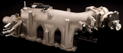
The air intake system of the Ford 3.5L GTDI engine is overall what you may expect to see on any other turbo engine. However, you may notice that the intake manifold is smaller than the naturally aspirated 3.5L. The reduction in size reduces the intake’s volume.
The reduction in volume decreases turbo lag. On SHO models, you’ll notice an odd, round plastic housing mounted to the intake snorkel. The housing will have an opening that is aimed at the passenger compartment.
Usually, little boxes hanging on the intake snorkel are there to reduce intake noise. In this case, it is a noise generator. The noise generator is intended to produce a “sporty” intake sound that is more appealing to the driver of an SHO vehicle.
Because of the pressurized intake system on a turbo engine, the EVAP purge system has a mechanical check valve added between the intake manifold and the purge valve.
The PCM tests the check valve each drive cycle by monitoring the fuel tank pressure sensor for a raise in pressure while the engine is under minimal boost. If the fuel tank pressure sensor reports a raise above a preset threshold, DTC P144C (EVAP check valve performance) is set.
If this code is set, the PCM may shut down turbo operation to protect the EVAP system and fuel tank from damage.
The PCV system on the 3.5L GTDI engine uses an “electric” PCV valve. An electric PCV valve still operates in the traditional mechanical method, however there is an electric heating coil made into the valve that prevents it from freezing in cold weather.
The PCV heating circuit is monitored by the PCM and will set a PCV circuit fault code if a circuit fault is detected. That much is nothing new when compared to the last few years of vehicle designs.
A new diagnostic method for the PCV system, however, is the added ability to detect a disconnected PCV hose and flag a specific code for it. DTC P2282 (air leak between throttle body and intake valve) is set.
The PCM sets this code if the air flow into the engine is greater than the air flow passing through the throttle body for a period of five seconds or more.
The GTDI engine does not use an MAF sensor. Instead it is a speed density system. Of course, as you know, a speed density system does not directly measure air flow. Instead, it estimates air flow based on throttle position, rpm, engine vacuum and the engine’s displacement.
Not having dealt with this code yet myself, I got a little curious to see what criteria the PCM uses to reach for this code. Not finding any code-set criteria, other than the part about the five seconds, I gave the flow chart a look.
The flow chart begins by saying that a P2282 is set due to unmetered air leaks. However, it doesn’t mention how it accomplishes this, such as using IAC trim (counts).
Though it doesn’t have an actual IAC valve, the PCM in a Ford electronic throttle control system still has some PIDs that are labeled “IAC trim” to show how far the PCM has to step high or low from factory preset throttle plate command to maintain desired idle.
In looking over the flow chart, I found that all tests were centered around the PCV valve and PCV hoses.
The flow chart for this code leads the technician to replace the PCM if no problem is found with the PCV, then drops the technician after that. If a technician lives by that chart, I can’t help but wonder how many PCMs will get blamed for a leaking intake gasket or brake booster.
Could a worn throttle plate and bore lead a tech to replace a PCM in this case? Time will have to tell what diagnostic oddities lurk that can set a P2282 that may not be found in flow charts.
This speed density system uses two MAP sensors.
The one in the top center of the intake is used in the load calculation and also contains the IAT2 sensor. IAT1 is a dedicated separate intake air temp sensor. The second MAP sensor mounts in the intake snorkel just upstream of the throttle bore and is used to measure boost pressure.
This system also uses a BARO sensor, housed inside the PCM and is non-serviceable. The BARO sensor is a major player in calculating load in this system.
The Ford GTDI engine is a twin parallel turbo system. The turbos are located on separate engine banks, but plumb together at the intake and work simultaneously.
The upstream O2 sensors on this engine are a “universal” O2, also referred to as a “wide band O2” or “air fuel ratio” sensor.