Although wheel speed sensors have served for many years as a basic component of conventional anti-lock braking systems, they’re playing a new role in providing data to safety devices like traction control, brake assist, braking distribution and vehicle stabilization systems.
The primary function of wheel speed sensors is to indicate differences in rotational speed among each of a vehicle’s four wheels.
The combined input of four-wheel speed sensors is part of the data that various safety systems use to calculate when and to what degree a safety device should be activated or deployed.
Getting Networked
To illustrate, wheel speed input might be shared among systems like the powertrain, automatic transmission, traction control, anti-lock brake, tire pressure monitoring, air bag, and speed-sensitive steering and body controls.
Each of these systems is networked via a bus communications system that allows one module to share wheel speed data with another.
To illustrate how wheel speed is shared among systems, some early tire pressure monitoring systems actually measure the increase in wheel speed of an underinflated tire and illuminate a tire pressure warning light to indicate an unsafe condition.
On the other hand, when a traction control system detects excessive wheel speed at one wheel or one drive axle, the traction control device may apply one brake to slow the spinning wheel or reduce ignition timing or throttle opening to reduce power output at the drive axle.
ESC
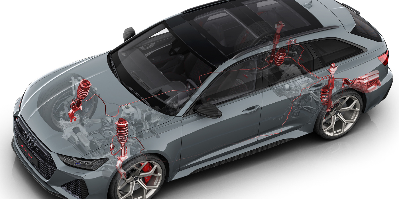
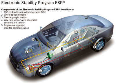
Electronic Stability Controls (ESC) are one of the most recent safety innovations being incorporated into vehicles. In brief, an ESC system uses a steering wheel position, yaw rate and deceleration sensor to determine if the vehicle is responding to driver input.
If a loss of traction is present and the vehicle is operating in an oversteer or understeer condition, the ESC responds by applying one or more brakes to help correct the over- or understeer condition, and reducing engine power to help correct a loss of traction.
 To accomplish an instant reduction of power, the ESC must incorporate a “drive-by-wire” electronic throttle that will reduce throttle opening independent of driver input. Using Toyota Vehicle Stability Control (VSC) terminology as a template, the ESC may also be networked with systems like the Electronic Brake Force Distribution (EBD), Brake Assist (BA) and Traction Control (TRAC) to bring the vehicle under control.
Wheel speed, quite obviously, is a primary input on each of these systems.
The Speed of Data
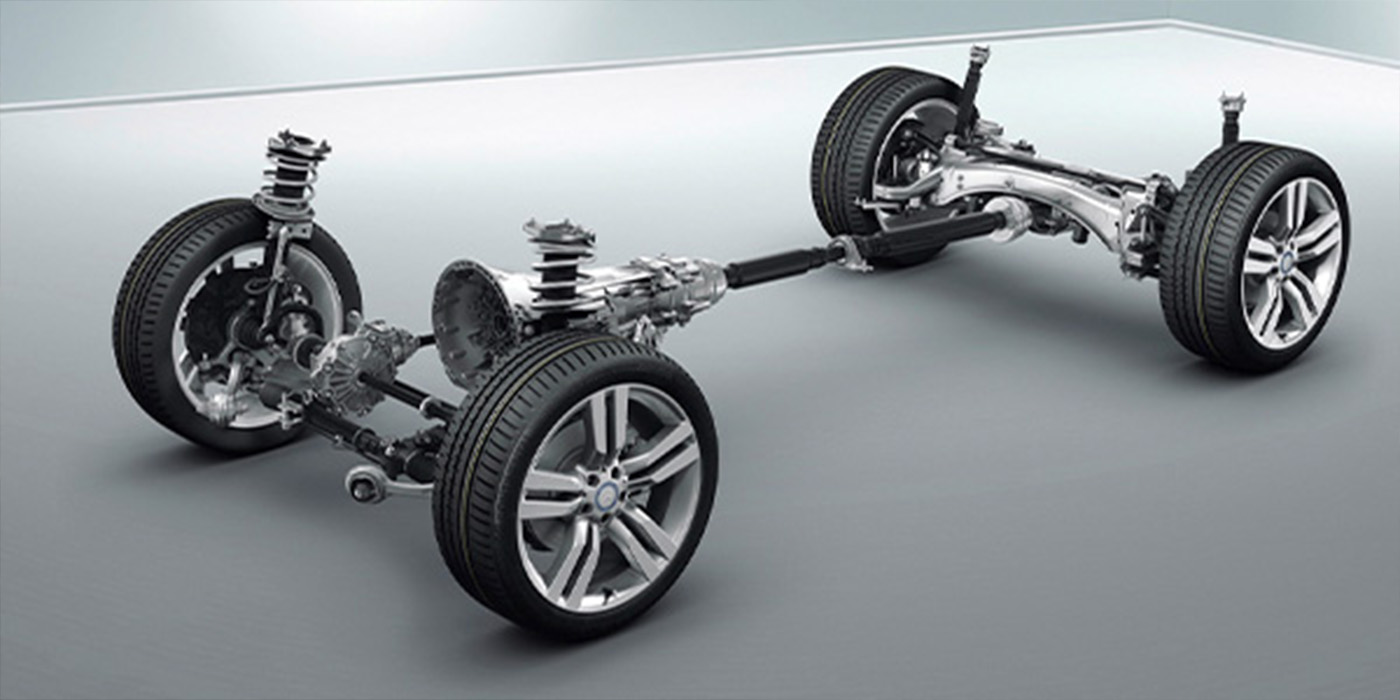
Since anti-lock braking systems were introduced several decades ago, inductive wheel speed sensors have been used to supply wheel speed data to the ABS module. The sensor itself is mounted on a stationary part like a steering knuckle and a reluctor or tone ring is pressed onto a rotating wheel component like an axle, brake rotor or wheel bearing hub.
 The tone ring is a gear-shaped part that is designed to induce an alternating current (AC) voltage in the sensor as the wheel rotates.
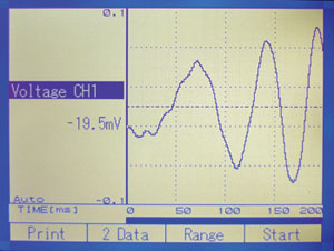
As each tooth of the reluctor passes the sensor, an AC voltage signal is produced that appears as a sine wave on a shop oscilloscope. Both the amplitude and the frequency of the voltage switch increase as the wheel gains speed. See Photo 1.
Failing Speed Sensor
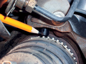
As one might suspect, the air gap between the sensor and reluctor can be critical. See Photo 2.
If, for example, the air gap is too great, the sensor might not produce enough voltage to be detected by the brake module.
A worn wheel bearing, for example, might increase the air gap enough to weaken the signal from the wheel speed sensor. When the signal weakens, the brake module might activate the anti-lock system prematurely because the lack of induced voltage indicates that the wheel is locking up.
Similarly, metallic debris from metal-to-metal contact between the brake pads and rotors might cause the wheel speed sensor to send erroneous data to the ABS and related modules.
To reduce the probability of this happening, some import manufacturers are integrating the wheel sensor with the wheel hub, which protects the sensor from air-borne debris. In any case, altered air gaps and contaminated wheel speed sensors usually present themselves as pattern failures in various vehicles primarily due to the way the various ABS computers and modules are programmed to interpret wheel speed data.
Breaking Away from Breakout Boxes
Many early ABS computers didn’t have enough capacity to display a data stream. Consequently, these systems were usually diagnosed by connecting a breakout box between the ABS module and the ABS wiring harness.
The technician would then use multimeter or labscope to measure wheel speed sensor resistance, voltage outputs and waveforms. Needless to say, breakout boxes are often difficult to connect, which can make breakout box diagnosis a time-consuming process.
Nevertheless, technicians can easily measure sensor resistance, voltage and waveform patterns using a breakout box.
When computing capacities and speeds were increased during the mid-1990s, scan tool-based diagnostic strategies came into use that display the speed of each wheel in miles per hour.
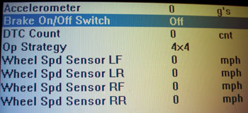
In some applications, 0 mph will be represented as a default value of, let’s say, 3 mph. In other applications, 0 mph will actually be displayed as “zero.”
As the vehicle accelerates, each wheel speed value should increase equally, with a variation of only 1 or 2 mph. If a wheel speed sensor is defective, the data stream will usually indicate 0 mph for that wheel. Data stream and trouble code analysis is the preferred diagnostic method simply because the sensors, wiring and wiring connectors aren’t disturbed or damaged during testing. See Photo 3.
Trouble Codes
If the wheel speed sensor fails on an intermittent or random basis, 1996 and newer OBD II systems will normally store a “C” code, indicating a failure in the chassis electronics.
To illustrate, C205/32 is the trouble code for a left front speed sensor on a Toyota VSC system. Similarly, a C1236/36 DTC indicates that foreign matter is attached to the tip of the left front wheel speed sensor on a vehicle equipped with the VSC system.
When diagnosing wheel speed trouble codes, it’s important to review all pertinent TSBs and other data before jumping to conclusions. In some rare cases, the ABS module might be receiving, but not “reading,” the signal from the ABS wheel speed sensor.
In other cases, the sensor itself might be developing an intermittent open or short-circuit condition.
In many applications, the analog or sine wave signal produced by the variable reluctor wheel speed sensor is converted to a digital signal that is sent to the PCM. Always keep in mind that a defective analog-digital (a/d) conversion might be a factor when pursuing any diagnosis involving input from wheel speed sensors.
Also be aware that some newer vehicles equipped with a stability control system might be using a Hall Effect wheel speed sensor in place of the conventional inductive wheel speed sensor. In contrast to the two-wire inductive sensor producing an AC sine wave, the Hall Effect is a three-wire, electronic switching device that uses an outside voltage source to produce a very precise square-wave signal to safety control devices.
Service Advisor
Several important precautions should be taken when replacing wheel speed sensors. For example, always note how the wheel speed sensor wire lead is routed on the control arm assembly so that the lead can be re-installed in its original position.
Next, make sure that the sensor and mount is cleaned before removal and, if so equipped, a new O-ring is installed to seal against moisture. If the sensor has an adjustable air gap, make sure that the gap is adjusted using the correct tools and specifications. To ensure a positive engagement of the locking tab and seal against moisture, lightly lubricate the connector and seal with silicone dielectric grease.
Last, reinstall the sensor lead exactly as it was removed and torque the sensor retaining bolt(s) to specification.
Above all, remember that accurate wheel speed inputs are critical to the reliable operation of all safety-related systems.