Ford Edge Brake Replacement Basics
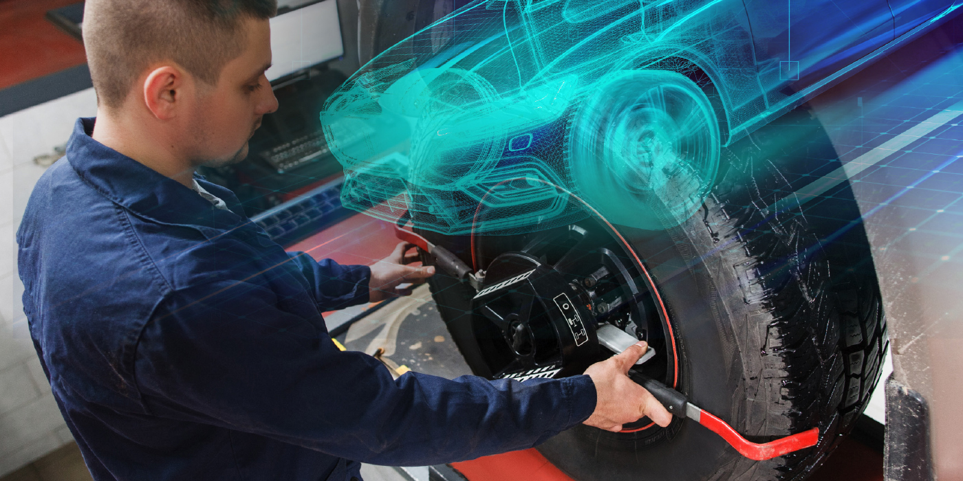
The Ford Edge is an SUV based on the CD3 platform. The brakes on these vehicles are straightforward and do not break any new ground. There were no major changes to the brake systems from 2007 to the current model. For the 2008 model year, ABS and ESC became a standard feature, as did a direct tire pressure monitoring system.
Unfortunately, the brake rotors on the Ford Edge do not have much material. It might be difficult to get at least one turn out of the rotors before they are under spec. Overall runout and thickness variation should be less than 0.001”.
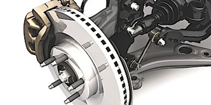
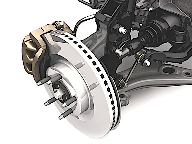
Front Brakes
The guide pin bolts are different sizes. The longer/bigger bolt is the upper guide pin bolt. Position the brake caliper and install the guide pin bolts. Tighten to 88 Nm (65 ft. lb).
The caliper bracket has a torque spec of 133 Nm (98 ft. lb).
Rear Brakes
The caliper bracket has a torque spec of 55 Nm (41 ft. lb.). The caliper guide pins have a torque specification of 26 Nm (19 ft. lb.). When replacing brake pads, make sure the slides are clean — do not over-lubricate with moly-style lubricants.
Parking Brake
Cable tension is adjusted in two locations. The first location is at the parking brake control, the second location is at the parking brake cable equalizer. The tension must be adjusted equally at both locations.
1. With the vehicle in neutral, position it on a hoist.
2. The dimension will vary depending on the amount of cable stretch. New cables require cycling the parking brake control 5-10 times to remove the cable slack. Adjust the parking brake control adjustment so the stud protrudes 8 mm (± 1 mm) from the top of the nut.
3. Adjust the parking brake cable equalizer adjustment nut so the stud protrudes 24 mm (± 1 mm) from the top of the nut.
4. Fully apply the parking brake pedal three times to verify correct operation of the parking brake system.
5. With the parking brake cable in the fully released position, brake drag should not be present.
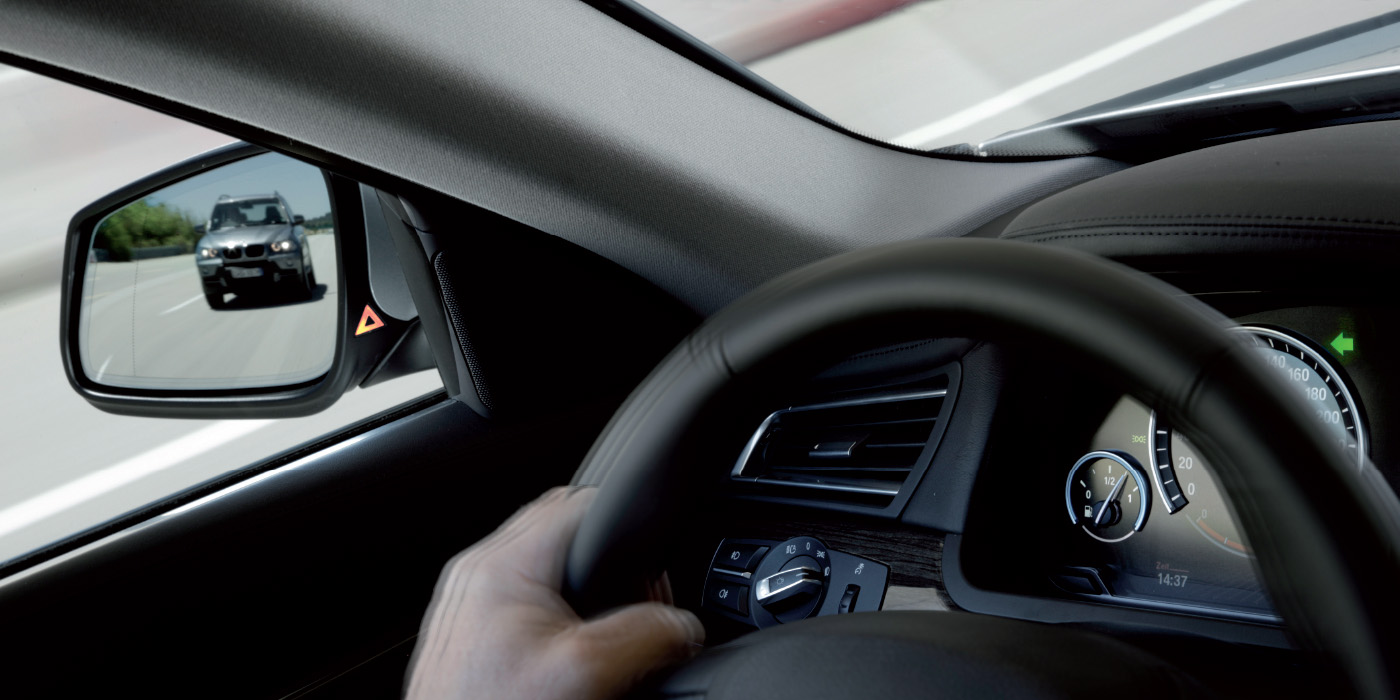
Some Ford Edge vehicles may exhibit brake drag from the rear wheels or from all wheels. Customers may notice an odor and/or reduced powertrain performance. In some cases, the driver may also note an integral vehicle dynamics (IVD) light after driving a given distance due to pressure noted in the module without a change in brake on/off (BOO) state.
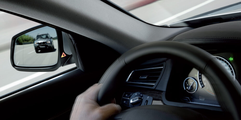
Rotate all of the wheels by hand to verify excessive force is necessary to turn wheels. To resolve the brake drag concern from all wheels, replacement of the BOO switch and adjustment of the parking brake cables is necessary.
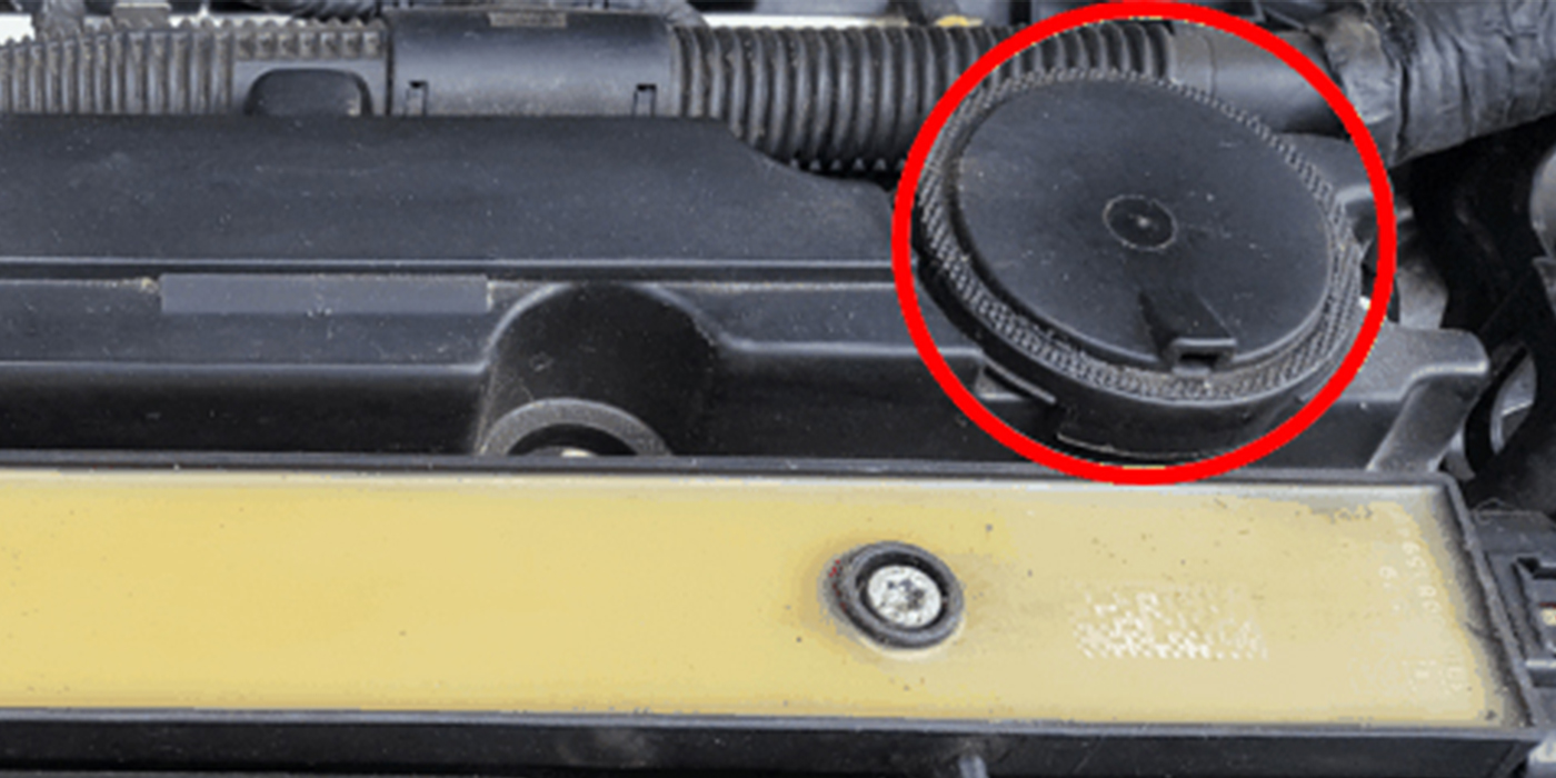
To replace the BOO switch, remove the stop lamp switch by rotating the stop lamp switch in the clockwise direction. If the brake pedal moves up during the removal of the switch, it means the pedal was being inadvertently held down by the stop lamp switch, thus keeping the hydraulic circuits pressurized. Disconnect the wire harness connector and replace the switch.
Installation of the new stop lamp switch must be done with the brake pedal at its normally installed and resting position. Do not pull up or push down on the brake pedal during stop lamp switch installation.
Courtesy Brake & Front End.