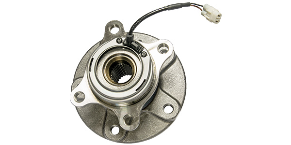

Firing the “parts cannon” at an active ABS wheel speed sensor code often results in misdiagnosis and an unhappy customer. It may start with the wheel bearing hub unit or wheel speed sensor. If those parts do not resolve the problem, the technician may fire the parts cannon at the ABS hydraulic control module. Typically, the customer’s patience and wallet runs out before the car is fixed.
From the heat-treated wheel bearing races to the microcircuit inside the ABS module that processes the signal, you need to understand the mechanical and electrical operation of this foundation technology that is critical to ABS, stability control and ADAS.
Codes
Wheel speed sensor codes come in two flavors — “electrical circuit” codes and “erratic” codes caused by conditions where the ABS module can’t rationalize the outputs of a given wheel speed sensor. Circuit codes for opens and shorts are easy to understand electrically. Codes for erratic performance can be caused by the physical relationship between the wheel bearing encoder ring and the wheel speed sensor. These codes are generated when the module processing the signal can’t rationalize the changes in speed when compared to the other wheels, or to the laws of physics. All wheel speed sensor codes are just the starting points of a diagnosis, and not a reason to order a part.
If the codes are electrical in nature, you need to confirm the resistive value of the wheel speed sensor, which should be between 1,000 and 2,500 ohms (top tip: check a known-good wheel speed sensor on the opposite side of the vehicle to get the exact value). Next, examine the integrity of the wiring. In addition, measure the output of the voltage or the presence of a bias voltage to confirm the operation of the module.
As stated earlier, erratic wheel speed sensor codes are set because the module can’t rationalize the output of a sensor. If the module sees a dropout of the signal from the sensor, it would literally translate into the vehicle stopping in inches and then accelerating back to that speed in a few inches. The software controlling the ABS knows this is not possible, so it sets a code.
Scan Tools and Wheel Bearings
Scan tools have come a long way in the past decade, such that improvements in sample rates and display capabilities can give technicians vital insights into a wheel speed sensor and the wheel bearing.
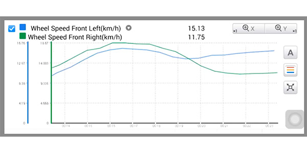
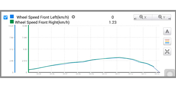
A modern scan tool can graph the output of multiple wheel speed sensors on a test drive. The output is how the ABS control module sees the wheel speed sensors. On the test drive, take a corner to see how the speed changes between the inside wheel and outside wheel. If you see sudden drops in speed, it is a sign that the air gap between the encoder ring and sensor has changed due to play inside the bearing.
If you are looking for a new scan tool, wireless connectivity with the OBD II port can make wheel speed testing easier if you are working alone. With a vehicle on a lift, you can observe wheel speed sensor data as you spin a wheel. Also, you can inspect a harness to see if poking or pulling changes the continuity of a circuit.
It is very difficult to repair WSS harnesses since the harness is in an environment that is exposed to water, heat and flying debris. The voltages measured by the next generation of wheel-speed sensors are so small that an alteration in the wiring can cause problems. This can lead to even more ABS diagnostic codes being set. Replace the harness because no amount of heat-shrink tubing or solder will work as well.
If you find a single WSS that is reading slower than the others, the cause may be one of two things: an oversized tire on that wheel or the sensor is not generating a pulse for every notch in the tone ring causing a lower than normal speed output. Things to check for here (besides the tire size) would be rusty, corroded or damaged teeth on the tone ring, or an excessive air gap between the tip of the sensor and the ring.
Something else to watch out for is mismatched parts. To produce an accurate signal, the sensor’s tone ring must have the correct number of teeth for the application. Make sure the tone ring on a replacement rotor, drum, axle shaft or wheel bearing is the same as the original. Often, the part will fit, but the OE changed the specification from the previous year or even changes in trim level will change the encoder ring.
Scoping Wheel Bearings
Using an oscilloscope or scope can measure more than just the output of the signal. Testing with a scope can show the health of the circuit with the wheel speed sensor on one end and the module at the other.
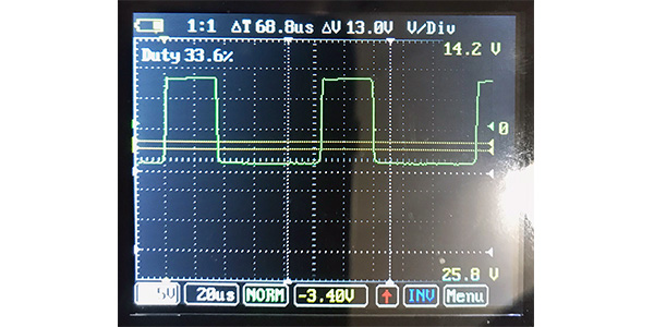
An active wheel speed sensor takes voltage from the ABS module (ranging from 8 to 12 volts) and changes the voltage signal by only 0.6 to 1.2 volts. The square wave’s peaks and valleys show the alternating polarity magnets in the encoder ring passing by the tip of the sensor. The faster the magnets pass by, the greater the frequency of the waveform, which is then translated into wheel speed by the ABS module. While this explanation might be oversimplified, it is enough knowledge to interpret the waveform.
Before you connect a scope, you need to better understand the circuit and bias voltage. The ABS module supplies voltage to the wheel speed sensor. The overall current levels of a wheel speed sensor circuit are low, but if the circuit is shorted to power or ground, there is potential to do damage to the circuitry in the module measuring small changes in voltage. There are no fuses in the wheel speed sensor circuit to protect the module. The module protects itself by sending out a low-voltage signal for a millisecond when it is first turned on and performs a self-check.
If the circuit is compromised by an open or short, the increased or decreased resistance will cause the voltage to drop or exceed specifications. If the readings from the bias voltage tests are correct, the module provides voltage to the circuit for operation. If the readings are not in the predicted range, the module will not supply power, and will set a code and deactivate the ABS and stability control systems.
Bias voltage tests also work to detect opens in the circuit. This is why if a wheel speed sensor is disconnected it will cut power and set a code. When the untrained technician does not see power at the sensor, he may think the module is defective and replace the module.
To read the voltage with the system on, you will have to back-probe a connector or use a bypass harness to clear the code from the ABS module to test the circuit.
When a scope is attached, you will have to adjust your voltage scale and cursors to see the 0.6 to 1.2 volt changes in the 5-12 volt range. The waveform should be clean and consistent. Missing peaks and valleys can indicate damage to the encoder ring. In some cases, the magnets of the encoder ring will attract metallic debris, causing the waveform to skip between peaks and generate codes for an erratic signal.
A low current amp clamp can be used to check active wheel speed circuits. It will not be able to see with the same resolution as a voltage test, but it can confirm if the module is providing power and even a bias voltage signal. The only problem is finding a section of the harness where the two wires are divided in the wheel well.
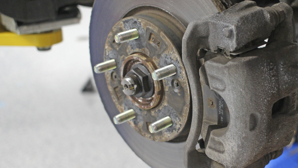
Mechanical Diagnosis
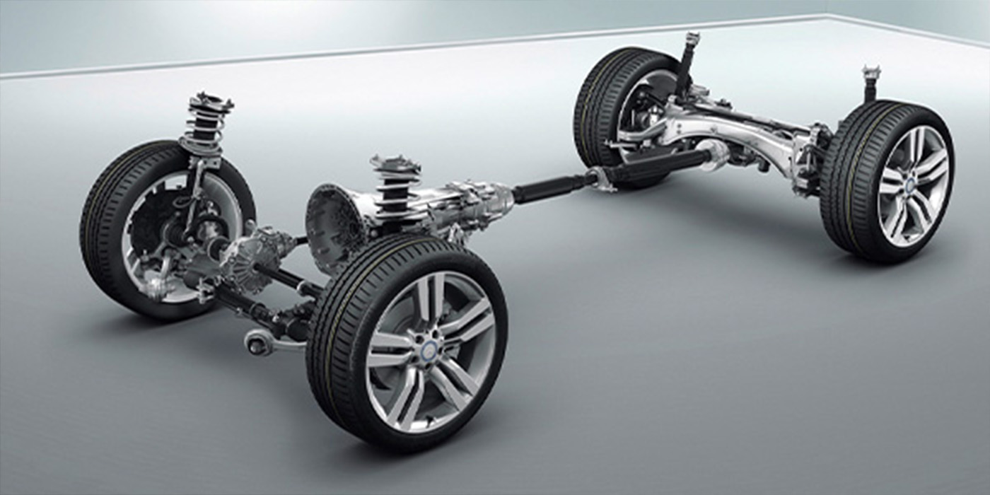
On a typical passenger vehicle weighing around 3,400 pounds, each pair of front-wheel bearings, as well as the rear-wheel or axle bearings, support around 850 pounds, depending on the weight balance and driveline configuration. If it’s a 6,000-pound SUV, each bearing might carry about 1,500 pounds. This load is concentrated on the relatively small bearing surfaces. To understand why active wheel speed sensors fail to report the correct speed of a wheel, it is necessary to understand what happens inside the bearing and the rolling elements, and how they change the relationship of the encoder ring and the sensor.
On a typical passenger vehicle weighing around 3,400 pounds, each pair of front-wheel bearings, as well as the rear-wheel or axle bearings, support around 850 pounds, depending on the weight balance and driveline configuration. If it’s a 6,000-pound SUV, each bearing might carry about 1,500 pounds. This load is concentrated on the relatively small bearing surfaces. Wheel bearing failures are event-related. Curb strikes, potholes and other incidents that may cause damage to the bearing surfaces and seals are what kill bearings, rather than an abundance of miles.
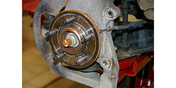
Back in the day, experiencing some play when tugging at 12 o’clock and 6 o’clock was normal. On most modern vehicles, it would take the world’s strongest man to feel any play.
Nowadays, bearing play is best measured by placing a dial indicator against the hub and turning the wheel. Refer to the vehicle manufacturers’ specifications, but as a rule, no more than 0.005” of play is allowed for most sealed wheel bearing and hub assemblies. This is due to the air gap tolerences between the encoder ring and sensor.
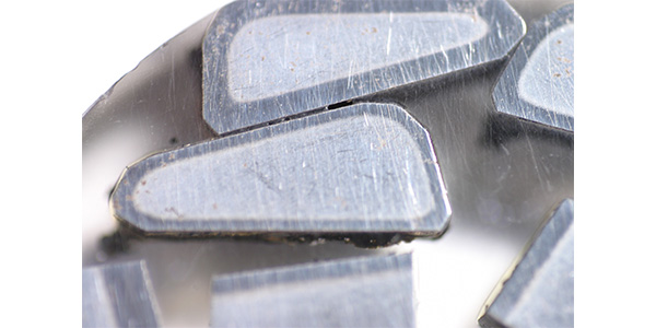
Most bearing components are heat-treated to harden the metal. But, the heat-treating can penetrate only so far into the metal. Once the bearing has worn through the treated layer, rapid and catastrophic wear occurs to the softer metal below. This type of fatigue failure is called “spalling.” The damage causes the metal to come off in flakes. The material loss of the races and rolling element creates play and noise. When the bearing play is great enough, the seal attached to the inner race becomes dislodged from the groove in the outer race. The movement damages the seal and the encoder ring that is embedded in the seal.
Article courtesy Brake & Front End.