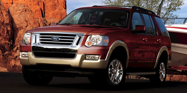
The fourth-generation Ford Explorer was a complete redesign of the platform and was the last to have a body-on-frame design. Overall, this is an easy vehicle to align with most of the adjustments built into the suspension.
Pre-Alignment Inspection
One of the most common failures on the front suspension is the sway bar links. They can break and cause noise and poor handling. The next most common failure is the bushings in the lower control arm. If the bushings are worn, the camber, caster and toe might be outside of the specifications. Another symptom will be inner or outer tire edge wear.
Inspect the ball joints for any signs of damage to the boots. If a boot is damaged, it is always a good idea to replace the joint. To test the lower ball joint, leave the wheel on and push up and down on the tire. To test the upper ball joint, grab on both sides of the upper control arm. The lower ball joint should have less than .8mm of deflection and the upper control arm should have no more than .2mm of deflection.
If you are dealing with Explorer with ControlTrac, pay special attention to the tires. If there is a great enough difference between tire rolling circumferences from side-to-side, it can cause binding and shuddering on acceleration and deceleration while the driver is turning. If the difference exceeds 1/2” side to side, the smaller tire needs to be replaced.
Ride Height
Checking the ride height on the Explorer can help to find worn out or damaged springs. This is important because the Explorer uses progressive springs in the front and rear. Measurements should be taken with a full tank of gas.
In the front, the ride height is the difference between the distance of the center of the bolt for the shock and the front inboard control arm bolt. Measure the distance between these two points from the ground and subtract the two numbers; this will give you the ride height. The measurement should be between 8mm and 16mm. For the Sports Trac it should be between 8mm and 21mm.
In the rear, the ride height is the difference between the distance of the center of the bolt for the shock and the rear inboard control arm bolt. The measurement should between 10mm and 95mm. Side-to-side measurements should not differ more than 10mm.
Front Camber and Caster Adjustment
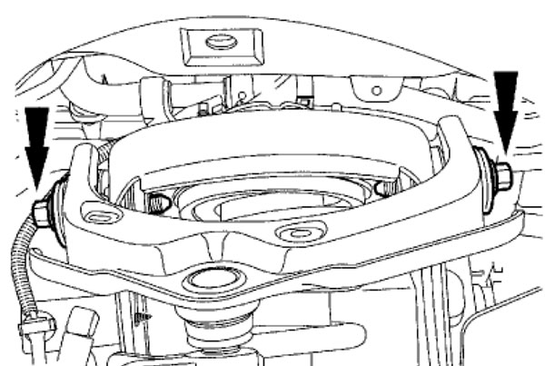
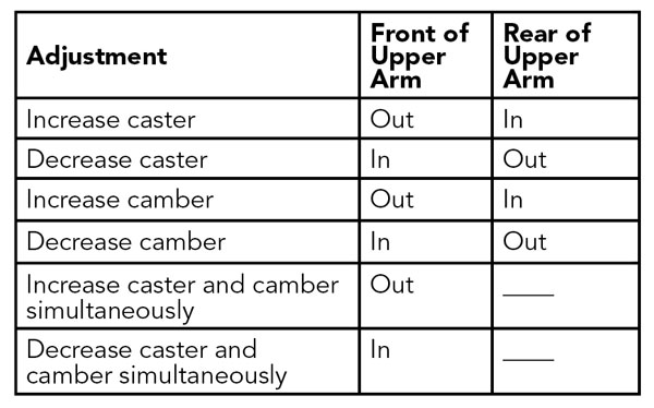
Front caster and camber are adjustable by the bolts that attach the upper control arm to the body. Loosen the upper arm bolt(s) and adjust the caster and camber settings. This adjustment has a lot of cross-talk between the camber and caster. When making adjustments that require moving both the front and the rear of the upper arm, move both ends of the arm equally.
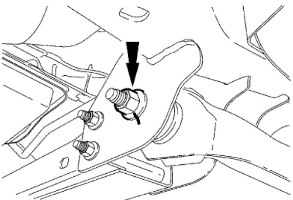
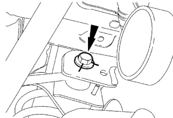
Additional caster adjustments can be made by loosening the lower arm rearward nut and adjusting the rear of the lower arm.
Ford recommends replacing the nut. Remove and discard the lower control arm rearward nut. Make sure that the weight of the vehicle is on the wheels and that the caster settings are not disturbed while tightening the nut.
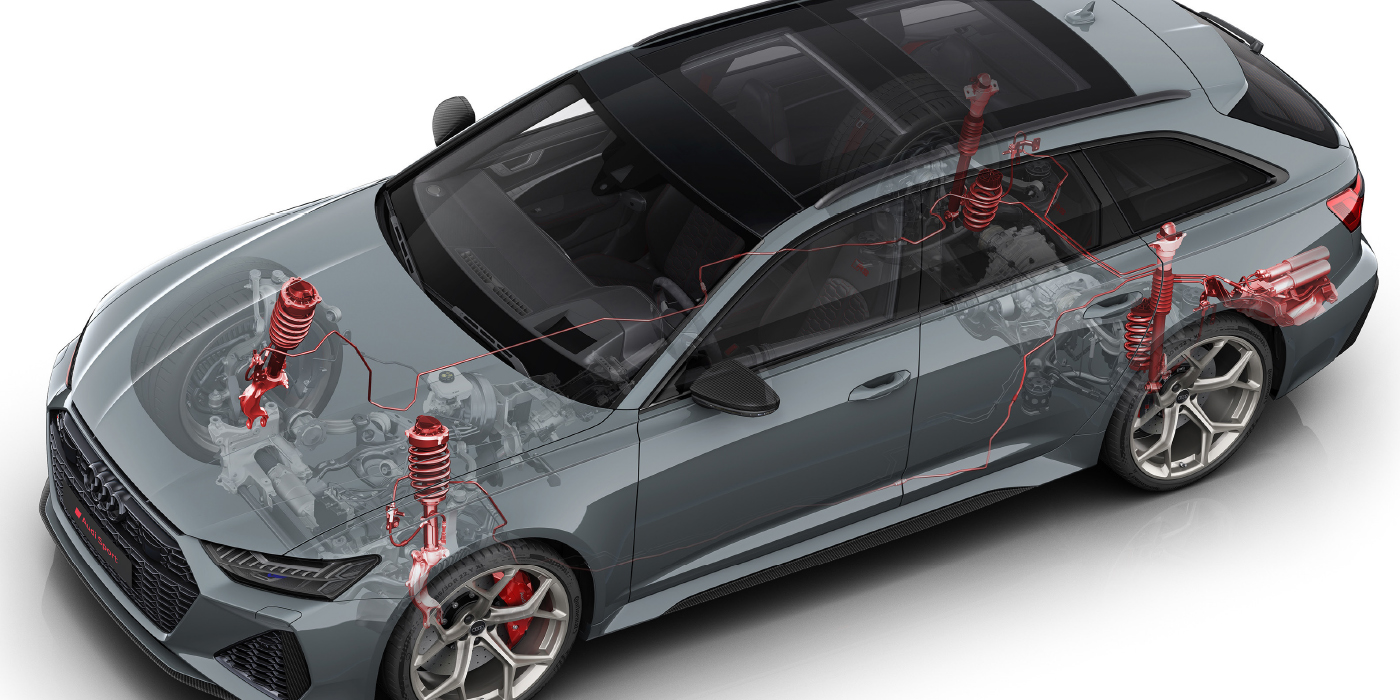
Rear Camber and Toe
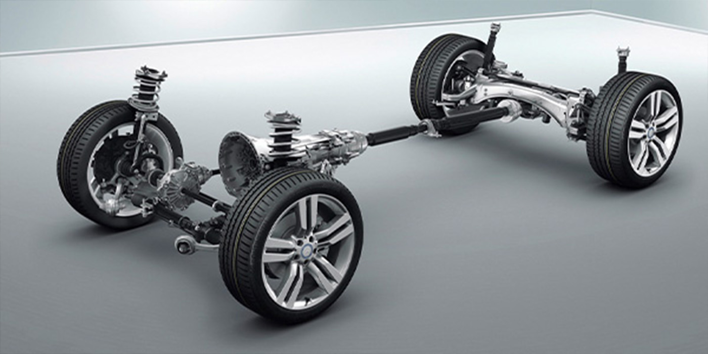
The rear suspension utilizes an independent short/long arm design. Rear camber can be adjusted by changing the position of the upper arm’s inboard bolt. On some vehicles, the factory did not install a bolt to adjust the camber by moving the bolt in the slot. A new non-flange nut will have to be installed. Note: 1mm of movement equals 0.24 degrees of camber.
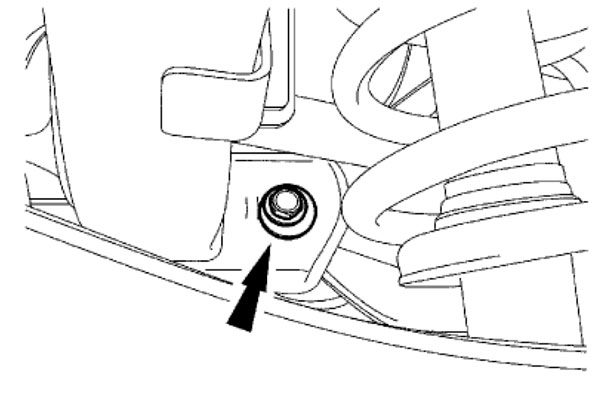
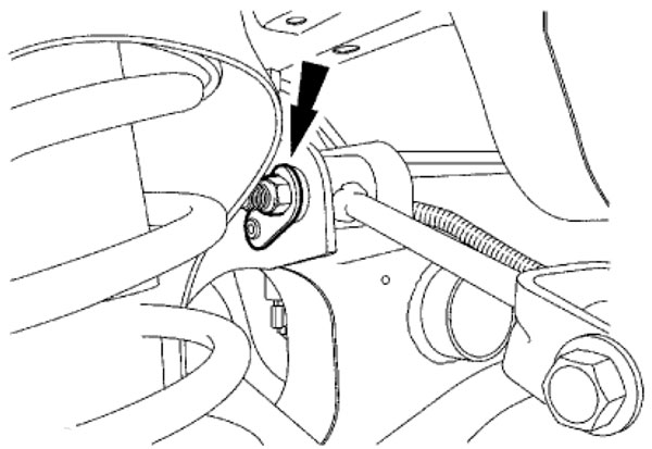
Rear Toe Adjustment Bolt
The rear toe is adjustable with a rear toe link. After the toe has been adjusted, the bolt needs to be tightened to 202 ft/lbs. Since the torque specification is so high, always check the toe readings after tightening thisw bolt.
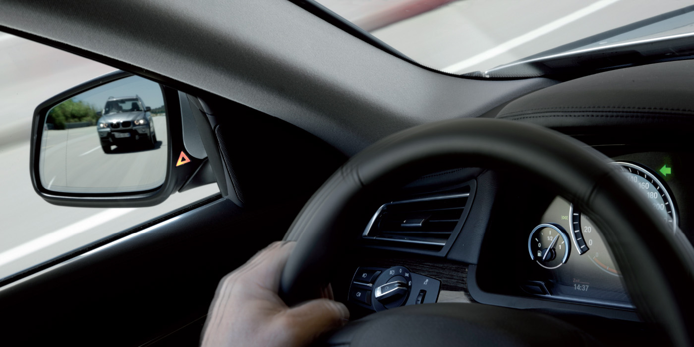
Steering Angle Sensor
The steering angle sensor measures the rate of rotation of the steering wheel. The sensor does not directly measure the straight-ahead position of the wheel. Instead, it uses other sensors like the wheel speed and yaw sensors to learn the steering angle. This is performed every drive cycle. If a great enough difference is seen between drive cycles, the system will set DTC 1998 for module calibration not complete, and turn on the DSC light in the dash. This can be caused by a change in the toe angle or if a component was replaced.
After alignment is complete, it is a good practice to recalibrate the steering angle sensor with a scan tool. This can prevent any lights from coming on when the customer drives away.
Article courtesy Brake & Front End.