In a 2009 study performed by the EPA, it was found that 80% of detectable leaks in 2004-2010 vehicles were discovered by the vehicle’s on-board evaporative testing (EVAP). The tests sealed the vehicles in a chamber and “hot soaked” them to simulate the car being run at full temperature and then parked. Sensitive sensors were then used to detect the presence of fuel vapor. Since these test chambers aren’t affordable, it is up to the technician to detect and find the leak.
On its own, any leak detection device can be a powerful tool to detect leaks. However, in the wrong hands, using these can lead to comebacks and parts being replaced needlessly. But, when one of these devices is paired with service information, training and most importantly a scan tool, it can lead to a more profitable and productive diagnostic process.
Just connecting the leak detection device to the EVAP test port or gas filler neck and cranking up the pressure to look for leaks is not the proper way to test the system. You will end up with a customer back in your shop with the same code, or you could wind up repairing leaks that are not leaks detectable to the system.
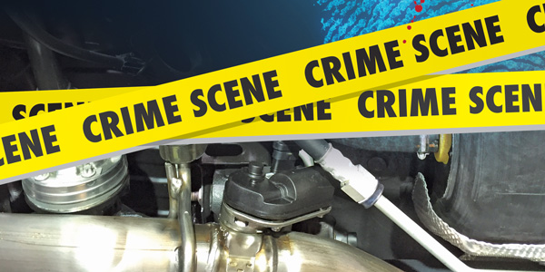
In order to test for leaks to resolve a code, you must think like the EVAP system and treat every EVAP leak like a crime scene. The second a hose is nudged or a connector is disturbed, a leak could be caused or sealed. When this happens, it could be difficult to confirm the source of EVAP code — in other words, the crime scene is now contaminated. Using a leak detection device is like dusting for fingerprints.
Decay
OBD-II evaporative emissions testing uses vacuum or pressure decay to measure leaks. In normal operation, the EVAP system performs testing by closing vent and purge valves to achieve the specified level of either pressure or vacuum. It then measures how much is lost over time. A pressure sensor measures the “decay.”
Some older systems use a bladder or diaphragm calibrated to detect a .0014” to .0020” leak. These systems then measure the amount of time it takes the device to react to vacuum or pressure and close or open an electrical circuit. If it takes too little time to make or break a connection, it would indicate a leak above the mandated size in the system and whether it is a gross leak or small leak. Later systems use pressure sensors mounted in the tank.
Pressure or vacuum for on-board EVAP testing can be generated a number of ways. A small electrical or vacuum pump can be used to create positive or negative pressure. The other way is to use changes in the temperature of the tank to generate vacuum. This is typically called “key-off” testing and requires certain conditions to complete the test. It also requires a few more sensor inputs and communication to perform the test and reset the emissions monitor. Some systems use algorithms of throttle position/load to determine how much fuel is being displaced by the pump and the vacuum generated to detect leaks when the vehicle is running. Also, ambient temperature and tank level play a critical role.
Modern systems use multiple tests to determine if there is a leak before setting a code. Most systems will do a quick check during start-up or at a specific speed to test the integrity of the EVAP system. This check will catch large leaks and test the function of the valves and sensors. Key off testing can be used to find smaller leaks more accurately.
For some key-off tests to be completed, conditions for ambient temperature, length of time parked and fuel level must be just right. Most late-model vehicles use key-off “natural” vacuum decay testing because it can accurately test for smaller leaks. This can prevent false codes from being set and the OEM from having to pay for excessive diagnostic warranty time.
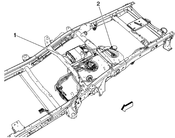
2. Evaporative emissions (EVAP) canister vent solenoid
Pressure
The key thing to remember when testing for a leak with a leak detection device is finding the right pressure. Connecting a leak detection device and cranking up the pressure to the highest setting is not a valid test. Often it will give you false positives and cause leaks in items that were not leaking in the first place. This can result in replacing components unnecessarily and not uncovering the real leak. Often, high pressure will cause leaks from the charcoal canister’s outside air intake valve and filter.
The canister will be replaced and the real leak will go undiagnosed. Once the EVAP system is starts completing key-off tests, the vehicle will be back with the same problem.
Scan Tools
Modern systems have up to three fuel vapor circuits in the EVAP system that are used to purge, isolate, vent and test the system for leaks. These solenoids are controlled by a module and can generate codes if an open or short is detected or if an action did not generate the expected result for the EVAP sensor in the tank.
In order test the entire system, it is necessary to set the positions of the purge, vent and other valves to fully seal the system. To do this requires a scan tool that can bi-directionally use Mode $08 data to control the EVAP solenoids. On some non-factory scan tools, it may take some time to find the correct menu to control the EVAP system.
Another advantage of a scan tool is using Mode $06 data to monitor pressure or vacuum sensor data from the EVAP pressure sensor. This information can be used to double-check the information coming from the leak detection flow meter.
A 2009 EPA study that took place in Colorado found that 70% of evaporative leaks were due to deterioration of the evaporative system. The other 30% of leaks were beyond the manufacturer’s control due to tampering and missing caps.
Article courtesy Underhood Service.