Cylinder Sealing: The Art of Measuring What’s Happening Now
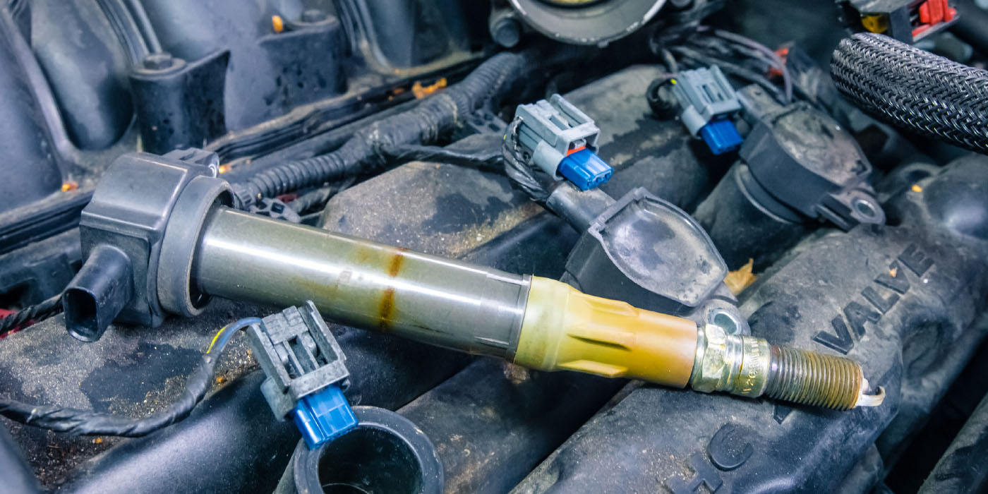
Cylinder sealing is the name of the game if you’re diagnosing compression problems on a modern engine equipped with variable valve timing (VVT) and gasoline direct fuel injection (GDI). Either system requires good cylinder sealing to optimize performance at high engine speeds. And, thanks to the lack of easy spark plug accessibility on most models, the conventional cranking compression and cylinder leakage tests have become time-consuming and often inaccurate. It’s obvious that modern engines require a more accurate method of testing cylinder sealing.

MODERN ENGINE DESIGN
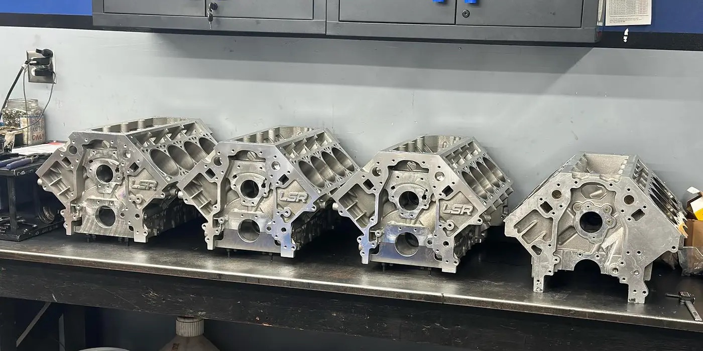
To reduce rotating friction and increase running compression, modern engines mate low-tension piston rings with precision-bored cylinder walls. To allow low-tension piston rings to effectively seal combustion gases and crankcase oil, the cylinders must be perfectly round and without undulations or “waves” along the length of the bore. Some engines are actually bored with a thick torque plate bolted to the block head gasket area to duplicate the normal cylinder distortions imposed by the cylinder head and main bearing cap bolts.
It follows that imperfections in the cylinder wall surfaces, worn valve guides and sticking or worn piston rings tend to aggravate cylinder sealing and oil control issues at higher engine speeds. Microscopic droplets of oil passing through the piston rings can actually cause detonation on some GDI engines, which severely damages the pistons and rings.
Some manufacturers also use high-silicon content hypereutectic pistons to reduce skirt clearances which, in turn, reduces piston rock at higher engine speeds. It’s not unusual nowadays to see .001˝ skirt clearances on many engines. Due to the high silicon content in the aluminum, the domes of hypereutectic pistons run very hot, which often requires more end-gap on the upper compression rings.
Modern engines use aluminum cylinder heads with alloy valve guides pressed into the casting. Valve guide clearances have been reduced to ensure that the valve makes full contact with the valve seat at higher engine speeds. To gain perspective on cylinder sealing testing, let’s begin by reviewing conventional compression testing methods.
TESTING PRECAUTIONS
Whenever a spark plug is removed, flakes of carbon are often caught under the exhaust valve seats. Although more time-consuming, the correct method is to loosen and re-torque the spark plugs and snap-throttle the engine a few times to clear loose carbon before performing a cranking compression or cylinder leakage test.
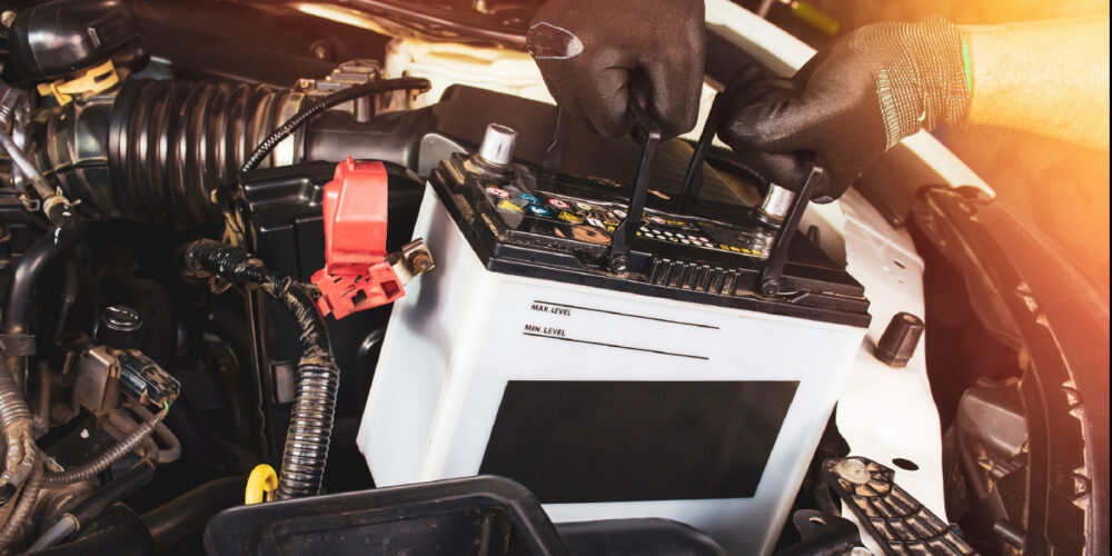
Weak batteries also affect the accuracy of any mechanical or electronic compression test. Before testing compression, verify the battery’s state-of-health (SOH) and state-of-charge (SOC) and clean the battery terminals to ensure full cranking amperage at the starter.
Cranking Compression – Cranking compression testing requires the throttle to be blocked partially open to allow each cylinder to breathe. If all cylinders test equally low, a valve timing problem or excessively worn piston rings are indicated. Worn valves, valve seats and valve train normally cause uneven compression. If only one cylinder has low compression, a burned exhaust valve, broken valve spring or broken piston rings are indicated.
Dry/Wet Compression Testing – The classic wet/dry compression test is intended to detect worn piston rings by comparing cranking compression between a “dry” cylinder and “wet” cylinder. A wet cylinder is created by squirting a teaspoonful of engine oil through the spark plug hole to temporarily seal worn piston rings. But let’s consider that it’s nearly impossible to distribute a small amount of oil evenly around the piston rings, especially on V-block engines. Introducing even a teaspoon of oil into a small-displacement cylinder will also increase the cylinder’s static compression enough to skew test results.
Finding TDC – Cylinder leakage testing requires finding exact TDC of a piston. In some hard-access situations, I have used a companion cylinder on the exhaust stroke to locate TDC on the cylinder on the compression stroke. If the combustion chamber configuration and space allow, a long, thin screwdriver can be used to “sense” when the piston reaches TDC.
I’ve also connected an accurate pressure/vacuum gauge to a compression gauge adapter with the Schrader valve removed. It takes a little practice, but as the piston approaches TDC, the gauge will show positive pressure. When the piston arrives at TDC, the gradual pressure build-up will suddenly stop. As the piston passes TDC, the cylinder begins to draw a vacuum. It takes a little practice, but this method can accurately locate TDC. This test is also useful for detecting mis-located timing marks and slipped harmonic balancing rings as well.
Cylinder Leakage – Leakage gauges use a metered orifice to create a differential between shop line pressure and cylinder pressure. The cylinder leakage gauge translates the difference between shop line pressure and cylinder pressure into percentages of cylinder leakage. In general, we’re looking at a maximum of 20% leakage on a 4-inch or larger cylinder bore. Since the tester orifice is fixed, the actual percentage of leakage can significantly vary between big-bore and small-bore engines. In my experience, the most effective use of leakage testing is to verify cylinder sealing on freshly assembled engines.
Running Compression – The running compression test is done by starting the engine with a professional-grade compression gauge installed in the cylinder. While we’re not looking for specific numbers, let’s say that running compression at idle for an average engine is roughly 80-90 psi. A wide-open, snap-throttle test should drive running compression well over 100 psi.
In the running compression test, we’re looking for variations in idle and snap-throttle compression readings among all cylinder readings. If running compression values vary significantly on one or more cylinders, a cylinder breathing problem caused by worn camshaft lobes, weak/broken valve springs, broken/dislocated rocker arms or broken cam lobe followers is indicated.
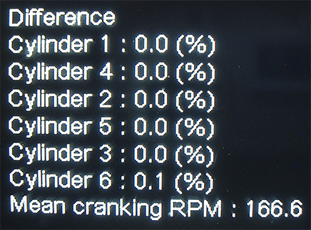
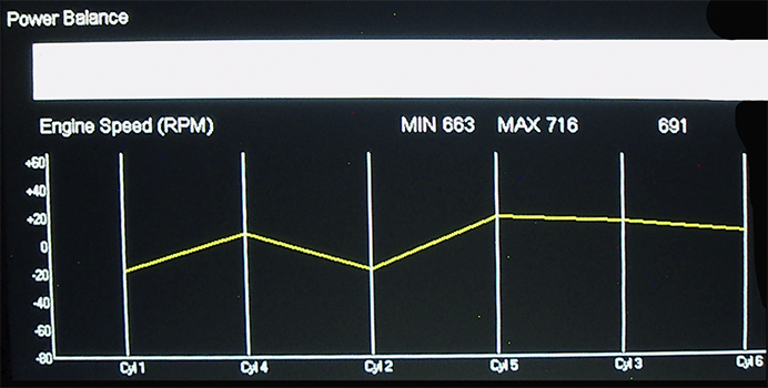
Cranking Amperage – If you’re familiar with a lab scope and have an inductive amp probe with at least a 400-amp capacity, first remove the fuel pump relay to disable the fuel injectors. Crank the engine to discharge residual fuel line pressure. On higher-capacity amp probes, one millivolt (mV) equals one psi. The lab scope display will indicate peak cranking amperage in millivolts as each piston approaches TDC compression stroke. The peak amperages for an engine in good condition should be equal. To identify a cylinder with a low amperage peak, connect a trigger pick-up to #1 spark plug. Count back through the firing order to identify the weak cylinder.
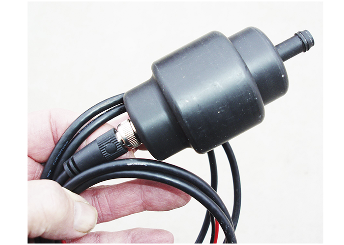
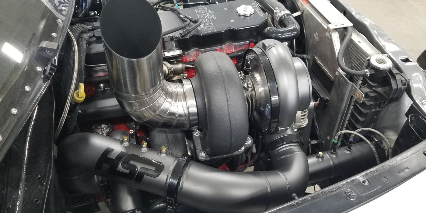
Transducers – A pressure wave transducer can also be connected to a lab scope to detect irregularities in relatively small pressure waves that occur inside intake or exhaust manifolds (see Photo 4). Using a trigger lead connected to #1 ignition primary or #1 fuel injector allows a technician to correctly identify the offending cylinder in the firing order. When connected to the dipstick tube, a pressure wave transducer coupled with a trigger pickup can also be used to identify above-normal piston ring leakage on individual cylinders. Either of the above methods require good lab scope skills and a working familiarity with waveform interpretation.
Article courtesy Underhood Service magazine.