As fuel injection took over, the first electric fuel-pump circuits were just a relay and fuse on the power side and an ignition switch on the control side. Control over the fuel pressure was performed with an analog regulator that adjusted for loads with a vacuum signal.
The fuel pump operated at full battery voltage no matter the load on the engine. This is not good for the life of any electric pump, and it caused significant noise inside the vehicle. It also required a return line to the fuel tank, which presented many difficulties for the EVAP system in detecting small and large leaks.
The earliest effort to improve fuel pump life was to install a series of ballast resistors. As the load on the engine changed, the resistor would be switched. It worked a lot like a resistor motor controller for a blower motor.
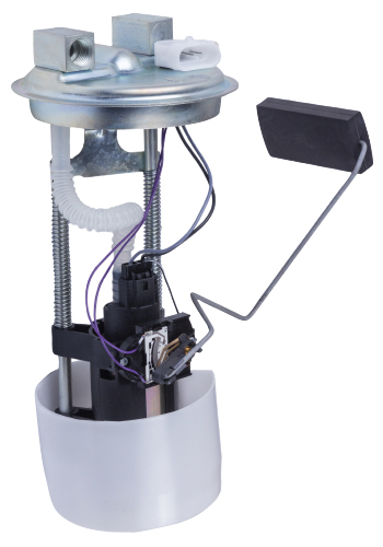
The regulator on the fuel rail not only controlled fuel pressure but also volume, by controlling the flow of fuel with a diaphragm, springs and vacuum.
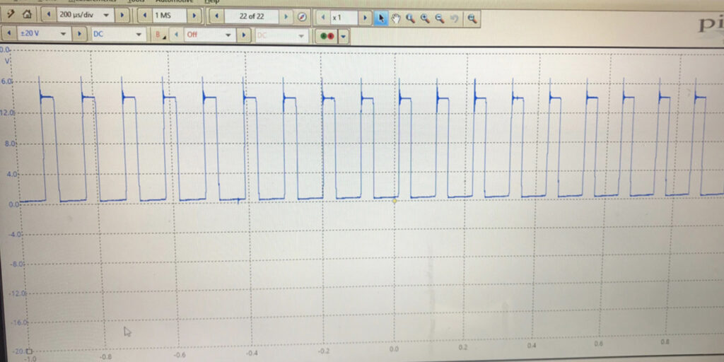
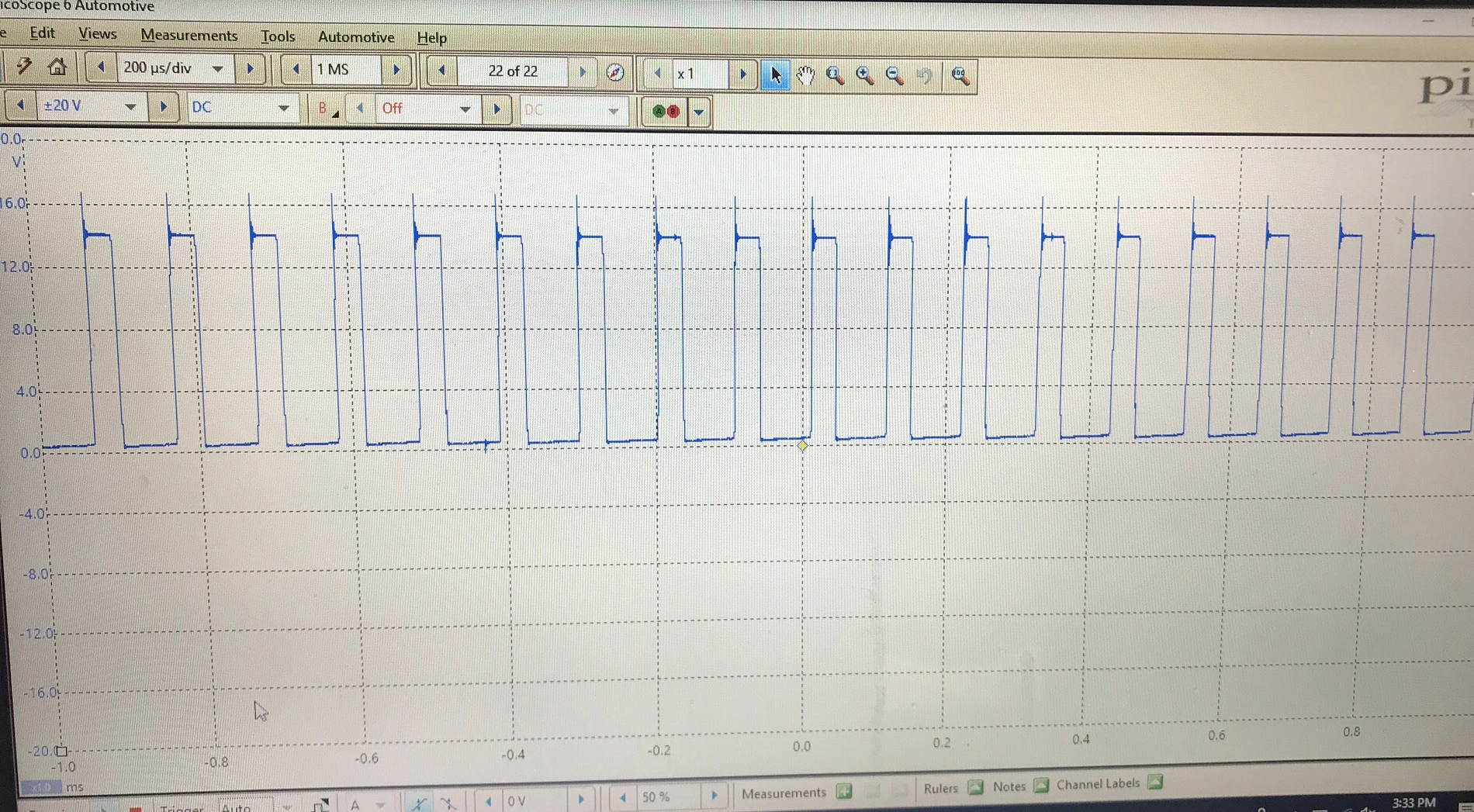
The major shift occurred when fuel pumps began to be controlled with pulse-width-module voltage. The fuel pump is driven by a signal that changes the power to control the speed of the motor and pressure delivered to the fuel rail during the duty cycle. The duty cycle is the measured period of time it takes for a signal to complete an on-and-off cycle expressed as a percentage. On some vehicles, you can view the percentage with a scan tool.
The driver for these fuel pump circuits is typically part of the engine control module. As engine loads and fuel trims change, the duty cycle increases or decreases.
Manufacturers have moved the driver for the fuel pump to modules in the rear of the vehicle. Some manufacturers moved the control of the pump to a rear electronic module; some moved it to a dedicated fuel tank module that also performs EVAP control.
As the control for the fuel pump moved to modules, codes for fuel pumps became more common. Some of the most common codes you will see are codes for the fuel pump circuits. These typically indicate that the circuit is open or the voltage is too high or low, which indicates short or high resistance in the circuit. Some of these codes are generic, but if the module is separate from the engine control module, you could be dealing with manufacturer-specific codes.

Fuel pressure should stay in a 3-5 psi range as load and engine speed increases and decreases. What will change is the duty cyle of the fuel pump.
The module that drives the fuel pump is typically looking for data PIDs from the engine. The data PIDs for fuel pressure can be critical in a diagnosis of a fuel pump and can save technicians from hauling out the fuel-pressure gauge and the assorted fitting to make a connection. Some vehicles have also eliminated the test port on the fuel rail. But how do you know if the fuel-pressure sensor is bad?
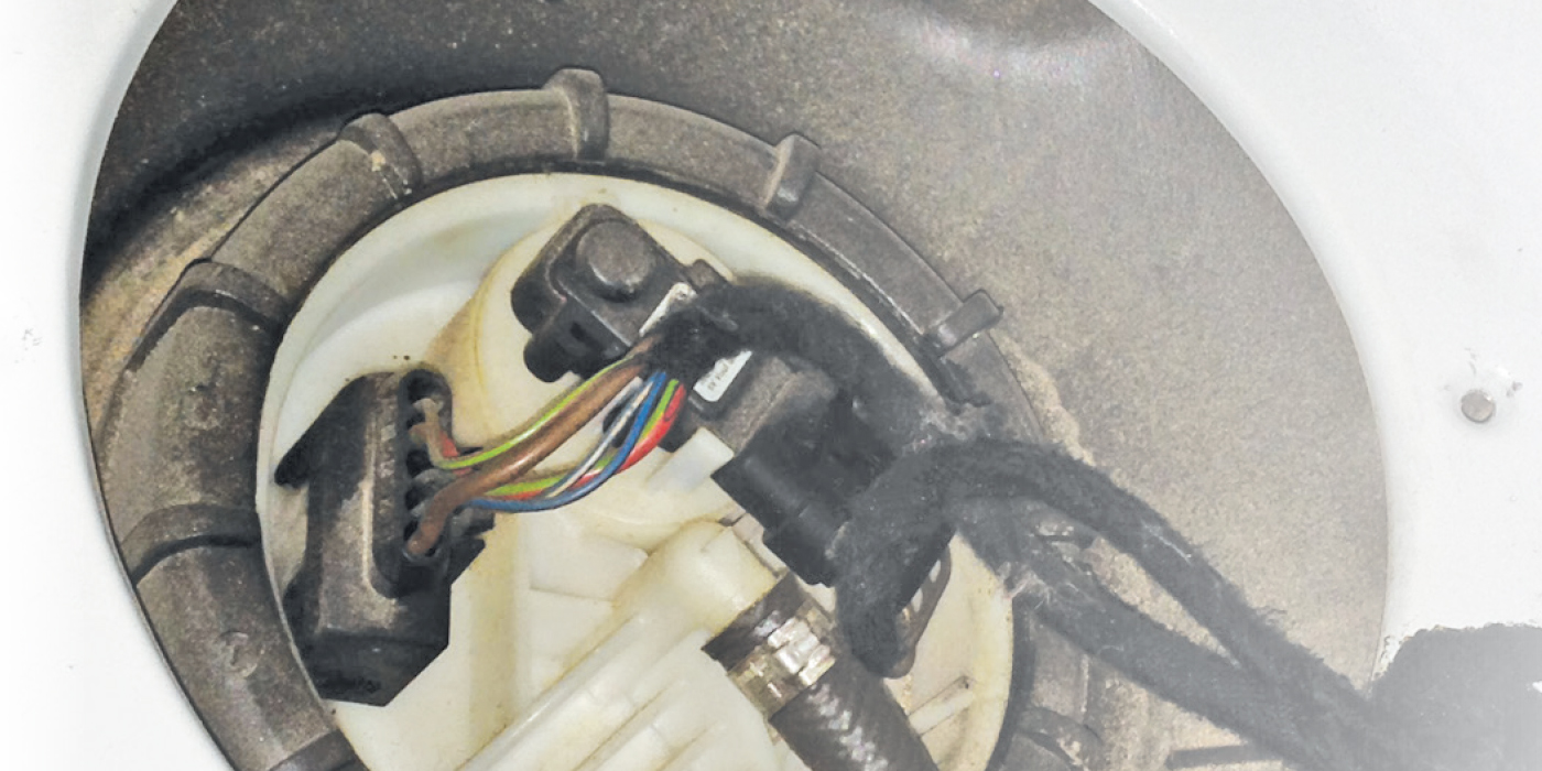
The fuel-pressure sensor usually has three wires and operates on five volts. As the fuel pressure increases, the resistance changes. The sensor monitors fuel system pressures and the performance of the pump. If the sensor is not getting a clean five volts, the voltage on the signal side will change. On some systems, this could cause the pressure to read lower than normal and create some fuel pump performance codes.
Observing the fuel-pressure PID during a test drive can give technicians insights into the health of the pump. If the pressure drops suddenly when accelerating, it could be a sign the pump is failing. The pressure should not change much during differing engine loads and speeds. This is because the pump is responsible for providing the correct volume while the pressure remains the same. Fuel pressure for most vehicles should stay in a 5- to 10-psi range. But, techs should make sure to look at the service information for the specifications.
Other data PIDs used to regulate the fuel pump include the engine position sensors. Additional data used to control the pump could be the engine load and fuel requirements. The goal of these sensors is to provide the correct amount of fuel pressure at the fuel injector so when the fuel injector opens, it shoots an accurate amount of fuel into the cylinder with a proper spray pattern.
Sensing if there is a problem with the fuel pressure caused by a pump that’s not producing the correct pressure and volume might be detected in several data PIDs like fuel pressure and fuel trims. Drivability symptoms of a weak fuel pump might be a loss of power.
Some vehicles will record the fuel pressure as part of the freeze-frame data if a code is stored. This can help technicians track down an intermittent fuel pump problem.
Since the fuel pump module needs information for various sensors, it usually communicates on a serial data bus. If modules aren’t communicating, the fuel pump can’t be adequately controlled. The key to investigating these problems is to communicate with different modules to see which data PIDs are present and which ones are missing.
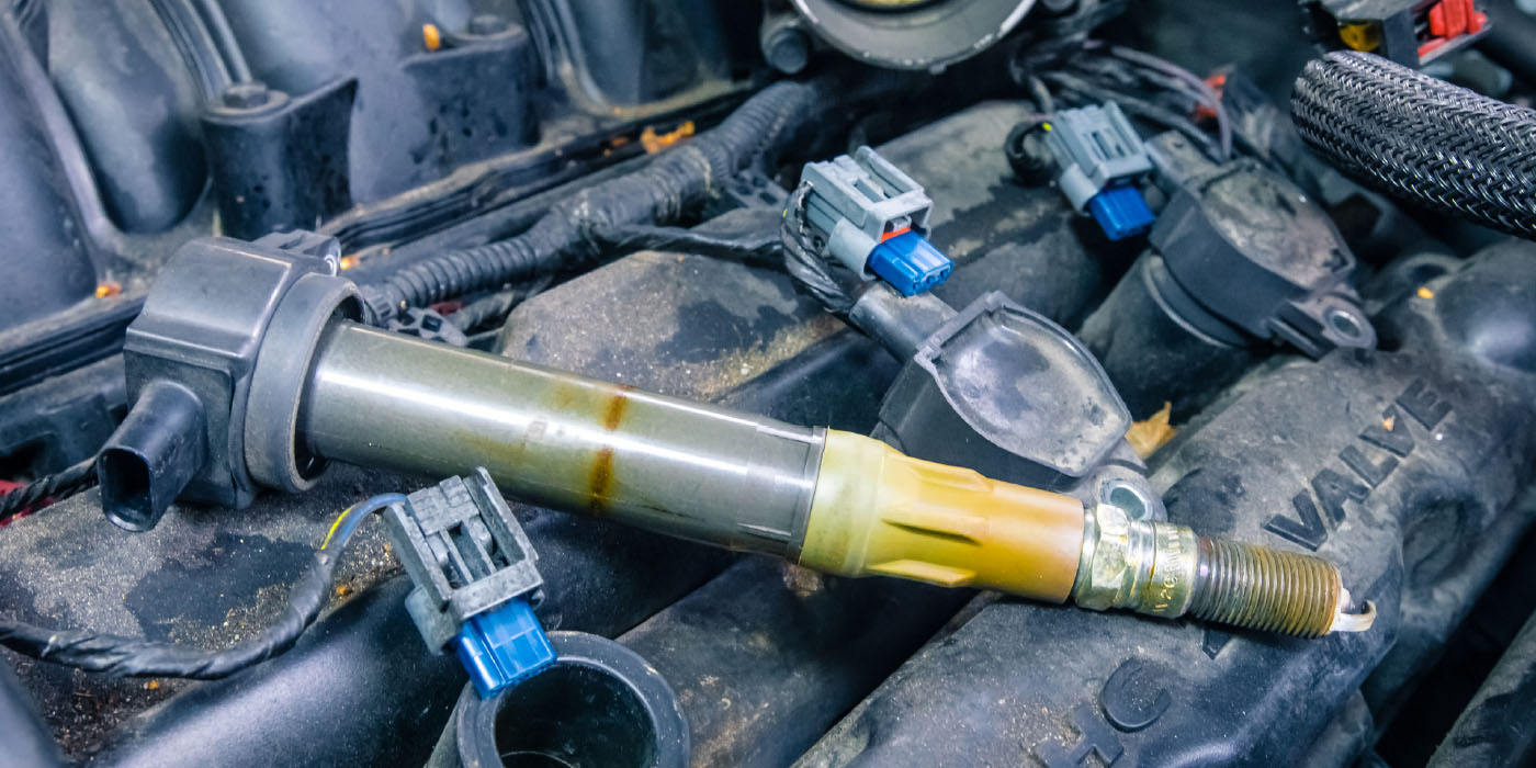
Direct Injection Fuel Pump Basics
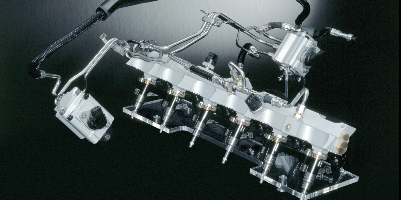
A direct injection fuel pump can’t increase its speed independent of the engine to increase its output or pressure, so it has to control the volume of fuel that is compressed. This relationship is what makes direct injection high-pressure fuel pumps a mystery to some technicians and even engineers. But once you understand the relationship between the pump and control solenoid, your diagnostic skills will grow.
High-pressure fuel pumps are mechanical and are typically driven by a camshaft. A lobe on the camshaft pushes on a follower or roller that moves a piston. The piston in the pump has two cycles, suction and compression. The solenoid on the side of the pump controls how much fuel is compressed during the compression stroke. During the suction cycle, the solenoid will allow fuel from the low-pressure side of the fuel system to enter the pump. As the piston starts to travel upwards, the solenoid will remain open. The fuel is pushed into the low-pressure side of the fuel system when open. When the solenoid is shut, the low-pressure and high-pressure side of the fuel system are isolated.
If there is low demand , the solenoid will remain open longer and a smaller volume of fuel is compressed. If there is a higher demand on the engine, the solenoid will close sooner, and a higher volume will be compressed. The length of time the solenoid is open will determine how much fuel reaches thel injectors.
The operation of the solenoid is engine-position dependent. The ECU and pump use the camshaft position sensor to know the position of the pump’s lobe on the camshaft. With engine position information, it can accurately time the events of the solenoid on the high-pressure fuel pump. If you hook up a scope to the solenoid, you will see a “peak and hold” signal that will change as demands on the engine change. On channel B, you can graph the camshaft position sensor to understand the location of the lobe.
The supply pump in the tank also can work as a limp-home pump if the high-pressure pump fails on some engines. When this happens, it will increase the output of the supply pump, open the solenoid on the high-pressure pump and change the open times of the injectors. This engine will have restricted performance. If the supply pump is weak or failing, it has been observed on some vehicles that the suction from the high-pressure fuel pump can suck fuel from the tank and keep the vehicle running, but with a great loss of power.
Diagnostic fundamentals for GDI are not that much different than conventional fuel injection systems. These systems inject the right amount of fuel directly into the cylinder. These systems are very efficient and are able to get the right amount of fuel into the cylinder so no fuel is wasted by not having to spray on the back of the intake valve.
This article is courtesy of Underhood Service.