Even for an experienced diagnostic technician, attempting to diagnose an intermittent misfire condition that occurs only under specific driving conditions can be a frustrating exercise. Let’s begin by getting the basics out of the way. As we know, the general causes of a misfire fall under the general headings of 1.) ignition, 2.) fuel density, 3.) compression and 4.) timing failures.
The Engine Control Module (ECM) detects a misfire by using the crankshaft position (CKP) sensor to measure the acceleration of the crankshaft when a cylinder fires. When a cylinder fires normally, the crankshaft momentarily accelerates, and when a misfire occurs, the crankshaft momentarily decelerates.
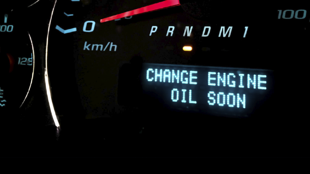
In brief, the PCM counts misfires at 200- and 1,000-rpm intervals and uses this data to sort misfires into Type “A” misfires, that can overheat and damage the catalytic converter, and Type “B” misfires that cause exhaust emissions to exceed the federal test procedure (FTP) standards by 1.5 times.
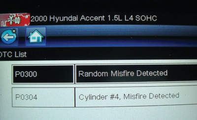
Type “A” misfires are indicated by a flashing orange “Check Engine” light (CEL), while Type “B” misfires simply illuminate the CEL. Both types of misfires will store a P0300-series diagnostic trouble code (DTC) in the diagnostic memory. As a point of clarification, the fourth zero on a P0300 code indicates a “random” misfire distributed among a majority of cylinders, whereas the fourth digit (ex. P0301) indicates which cylinder is misfiring.
With that said, the misfire detection strategy programmed into specific engine management systems will vary widely among vehicle models, model years and manufacturers. Remember also that a rough idle doesn’t always meet the criteria for storing a cylinder misfire code. See Photo 1.
Ignition Misfires
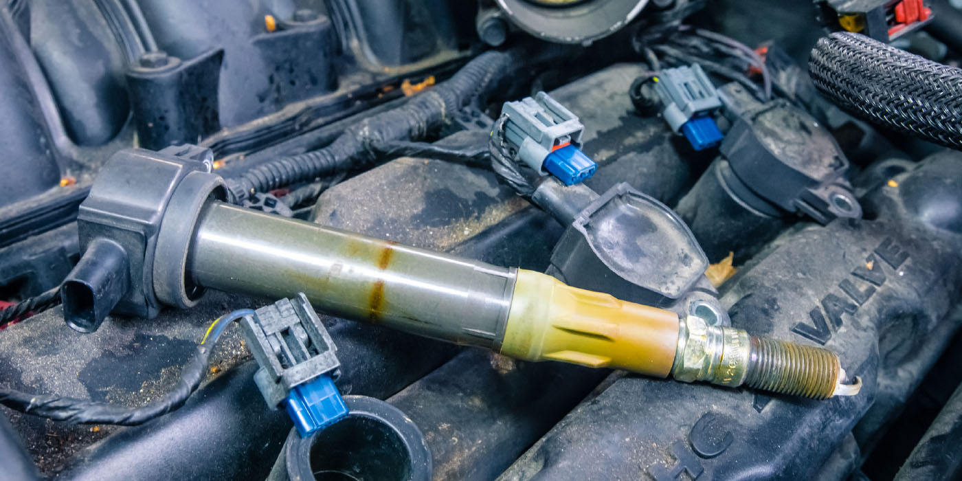
Intermittent ignition misfires can be caused by faulty spark plugs, spark plug wires, ignition coils and ignition coil drivers located in the ECM. Some intermittent misfires can be more easily detected if a scan tool displays an individual cylinder misfire count in its datastream, or monitors coil activity and variations in burn time and primary coil amperage. Since misfires caused by coolant leaking from cylinder head gaskets often depend upon engine temperature, they can become very intermittent. In most cases, the diagnostic tech must pursue intermittent ignition faults by visually inspecting parts for spark perforation or carbon tracking, or by using a labscope to monitor ignition activity.
Many intermittent ignition misfires can be prevented by using a rubber spark plug holding tool to keep the insulators clean when installing new spark plugs. Using an anti-seize compound is also an issue because the compound must be nickle-based. Manufacturers differ on whether or not to recommend the use of anti-seize, but most do not. Excess anti-seize compound can cause a misfire under load by spattering on spark plug electrodes. Lastly, always install a long-life spark plug that meets the OE manufacturer’s standards for heat range, shell plating and electrode design. See Photo 2.
Fuel Density Misfires
Fuel density misfires are caused by air/fuel (A/F) ratios that are too lean or too rich. A leaking intake manifold gasket or an intermittently clogged or inactive fuel injector, for example, can reduce the fuel density inside the cylinder to the point that it fails to support combustion. Intake manifold gaskets, especially those sealed with rubber O-rings, are often temperature-sensitive and can cause lean misfires when the engine is cold.
A disintegrating substrate in a catalytic converter can also cause intermittent misfires when the cylinders can’t draw enough air to support combustion. When dealing with an intermittent or “hard” cylinder bank misfire, it’s important to determine if the engine is equipped with a catalytic converter on each bank. Keep in mind that many in-line engines are now configured in the ECM with a “bank 1,” which is the front half of the engine and a “bank 2,” which is the rear half.
In many cases, an excessively lean or rich A/F ratio will be accompanied by short- and long-term fuel trims exceeding plus or minus 5% and a P0171/174 (lean) or P0173/175 (rich) diagnostic trouble code. Keep in mind that a rich A/F condition might cause a rough idle, but often won’t store a P0300-series code. Many P0173/175 “rich” trouble codes are mechanically caused by leaking fuel pressure regulators, leaking fuel injectors or excessive fuel pressure.
The more common P0171/174 “lean” codes are typically caused at higher engine speeds by faulty data supplied through the engine coolant temperature (ECT), barometric pressure (Baro), throttle position (TP), mass air flow (MAF) and oxygen sensors (O2). Examples include out-of-the-box problems like broken TP sensor ground wires or by loose debris floating in the MAF sensor housing. Intermittent P0171/174 codes can also be created mechanically by low fuel pump pressures or clogged fuel injectors when the engine is operating under load.
Compression Misfires
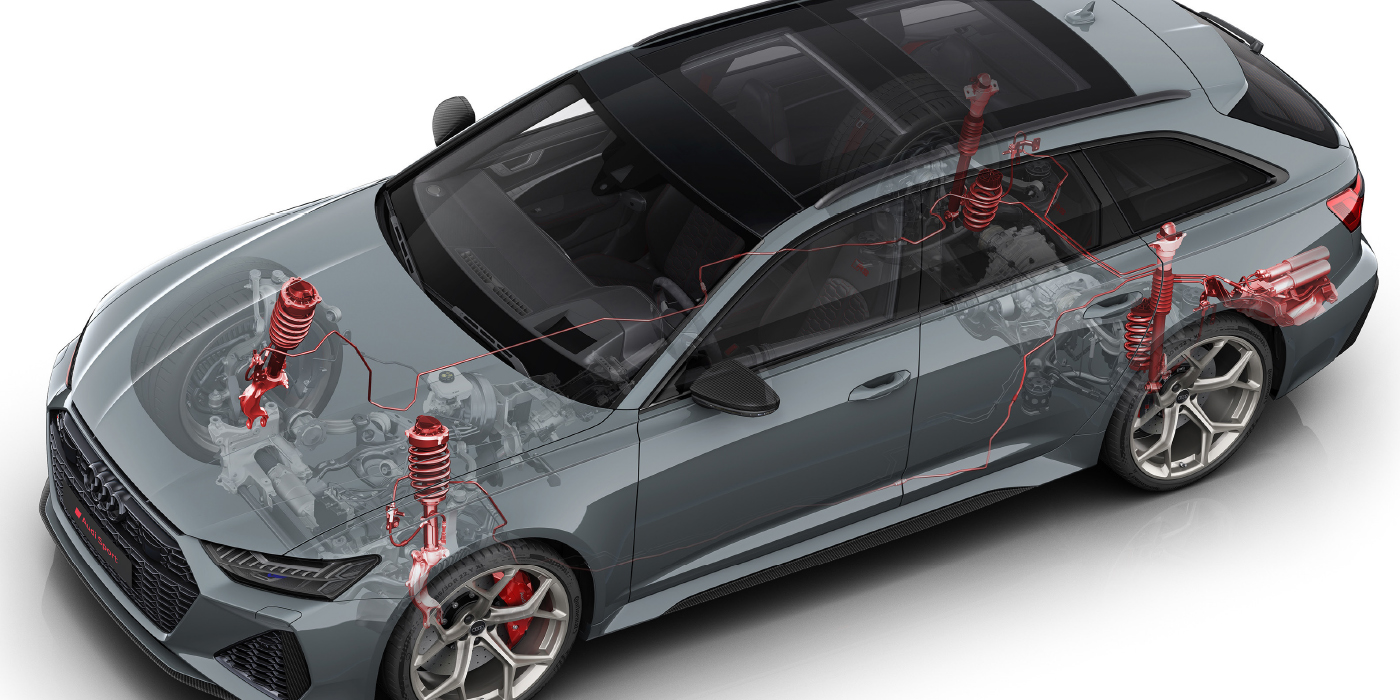
Compression misfires are most often caused by leaking intake or exhaust valves, mechanical valvetrain failure or incorrectly timed camshafts. Diagnosing an intermittent compression misfire can be tricky if the problem is caused by a marginal failure like a carboned-up intake valve seat or a broken valve spring.
In either case, the misfire might occur only under specific operating conditions. Engines equipped with variable valve timing (VVT) generally cause misfires on a single cylinder bank of a V-type engine if a cam phaser or solenoid intermittently sticks in position. On rare occasion, a sticking exhaust valve caused by insufficient valve stem oil clearances or a weak valve spring can also cause a very intermittent loss of compression and cylinder misfire.
Timing Issues
Obviously, over-advanced ignition timing can cause cylinder misfires. Excessively retarded valve timing won’t cause a misfire, but will cause a substantial loss of power. But since ignition timing on most modern ignitions is non-adjustable, any failure in ignition timing would be caused by a computational error in the ECM. Computed valve timing problems are less of an issue because an appropriate DTC is stored in the ECM’s diagnostic memory.
Scan Tool Tips
As mentioned earlier, the general causes of a misfire fall under the headings of 1.) ignition, 2.) fuel, 3.) compression and 4.) timing. Always begin any intermittent misfire diagnosis by using your professional scan tool to retrieve misfire codes and freeze-frame data. When diagnosing intermittent misfires, don’t forget to look at pending codes for indications of an individual cylinder misfire.
If your scan tool’s misfire history indicates multiple cylinder misfires, focus on the cylinder with the most misfire counts. The misfire counts on adjacent cylinders are often “sympathetic” misfires that will often disappear when the primary misfire is repaired.
Short-term fuel trim (SFT) numbers can be used to determine if the misfire is caused by lean or rich a/f ratios. Normal SFTs running about plus or minus 5%, or even as high as 10%, might not indicate a problem. But, for example, if the SFT is running high positive numbers at idle and returns to zero as the engine speeds up, you’re probably looking at a vacuum leak.
As mentioned earlier, negative SFTs indicating a rich A/F ratio might produce a rough idle, but won’t always produce a P0300 code. Keep in mind that the downstream, post-catalyst oxygen sensor can often be used to differentiate between an ignition- or fuel-related misfire. To illustrate, a misfire caused by a lean A/F mixture will drive the downstream voltage lower because an excess of oxygen is passing through the catalytic converter. In contrast, an ignition misfire will drive the downstream O2 voltage higher because raw fuel and oxygen is being oxidized in the catalytic converter.
Labscope Tips

Labscopes can be used to display secondary ignition waveforms through a special inductive probe. If you’re testing primary ignition, you should use an attenuated test lead to avoid damaging your scope. In any case, secondary waveforms are valuable for detecting bad spark plug wires and ignition coils. If available, your “movie” feature can be used to more easily detect intermittent cylinder misfires.
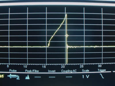
Current ramping the primary ignition system by using a low-amperage current probe to display the current rise through the coil primary circuit is the best method to detect a bad ignition coil because it’s non-invasive and provides a far more accurate indication of coil performance than do most primary or secondary displays. See Photo 3.
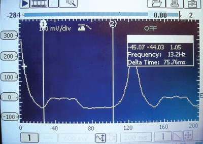
In-cylinder pressure transducer testing is an excellent method for accurately testing running compression and camshaft timing. While space doesn’t allow a more detailed explanation of scan tool and scope diagnostics, keep in mind that many excellent training books and videos are available through several reputable aftermarket suppliers. Practice makes perfect and collecting known-good data in your scan tool or scope memory for future reference is the best way of recognizing the various causes of an intermittent misfire. See Photo 4.
Propane Testing
When used with care, introducing propane into the intake system to enrich the A/F ratio is a quick and generally efficient method for diagnosing fuel density misfires. In brief, adding fuel will temporarily correct a lean-fuel condition caused by a vacuum leak or clogged fuel injector. Remember that when propane is added to intake air, the lean cylinder will return to normal, while the remaining cylinders will run slightly rich. Keeping it quick and simple is often the best way to diagnose any fuel-related intermittent misfire.
Courtesy ImportCar.