Installing new rotors without ever measuring and documenting the condition of the old rotor is like playing chicken with a comeback. Sooner rather than later, you will find a vehicle that will not be magically fixed by a new set of rotors. In fact, blindly replacing the rotors can cause you to falsely blame your parts suppliers.
Some people think that installing new rotors without measuring for runout will eliminate all possibilities of a comeback for noise, judder or pulsation. However, this myth creates more comebacks than it solves. It is a cycle for some shops that starts with blaming the new pads after the customer complains of a pulsation problem or noise.
When the customer is back for the second time, they start to blame the new rotors not being able to take the heat. It is not until the third time when someone pulls out a dial indicator and micrometer to find out the wheel bearing flange is the culprit. The first two comebacks they blamed on the quality of the pads and rotors, and it is not until the third visit that they see the problem was their own practices.
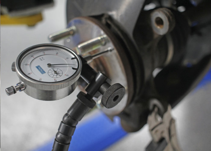
After the rotor is resurfaced or a new rotor is installed, the rotor should be measured for runout as a quality-control measure. A new rotor could have excessive runout when it is installed on the vehicle due to a stacking of tolerances.
Runout is defined as the amount of lateral (side-to-side) movement of the rotor as it rotates 360 degrees. The specification is usually provided as “TIR” or “total indicated runout.” TIR is defined as the runout measured on the vehicle or installed runout. This means that the rotor should be measured with conical washers and the lug nuts installed to the factory specification.
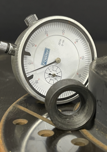
You could also call TIR the stacked runout of the hub/rotor/wheel assembly. All of the above factors add up to create the rotor’s TIR. This brings up an important point. The average allowable TIR specification for late-model vehicles is between 0.001 and 0.003 inches. This is the maximum allowed! Some manufacturers have specified 0.000 inches of runout. Runout will NOT cause pedal pulsation on vehicles with floating or sliding calipers and the caliper housing is free to move and the runout is not excessive.
Under these conditions, the caliper will “follow” the runout, such that the caliper housing will move in and out in relation to the runout. This movement will not cause the caliper piston to move. This is a key point to understand. No piston movement results in no fluid movement in the hydraulic system. If there is no fluid movement, the brake pedal won’t move or pulsate. So, a key point to understand is that runout generally does NOT cause pulsation. Runout causes thickness variation that leads to pulsation problems.
The main culprit of chronic pulsation was variations in disc thickness, or parallelism. The two friction surfaces of a rotor are designed to be parallel to one another within a certain specification. The allowable tolerance is known as parallelism. It is also known as the rotor’s disc thickness variation, or DTV. In order for the pad to stay in contact with the rotor, the piston must extend or be pushed back into the housing as force is applied. This creates the pulsation in the pedal that is most noticeable to the driver.
Every time the low spot passes by the caliper, hydraulic pressure at the caliper drops. This produces less braking force as this area passes by the pads. This also can affect braking distances.
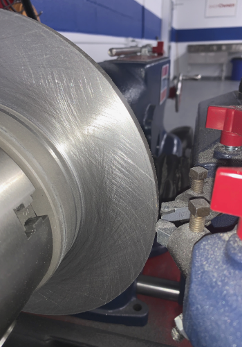
In some cases with excessive runout, a new rotor should be machined to match the vehicle. It has often been said that you should never machine new rotors. But, what if the runout exceeds the manufacturer’s specifications when the new rotor is installed on the vehicle? This is when it is permissible to machine a new rotor with an on-the-car brake lathe. This helps to match the rotors to the hub flange.
Using an on-the-car lathe can help to reduce runout on new rotors. The main advantage of these lathes is that they are able to cut a rotor in its operating plane. This means that the rotor is machined to match the hub.
Even if you use new rotors, your chance of a pulsation comeback could be greater than if you left the old rotors on the vehicle. Runout in the hub and new rotor can stack up to cause DTV – the main cause of pulsation – within a few thousand miles.
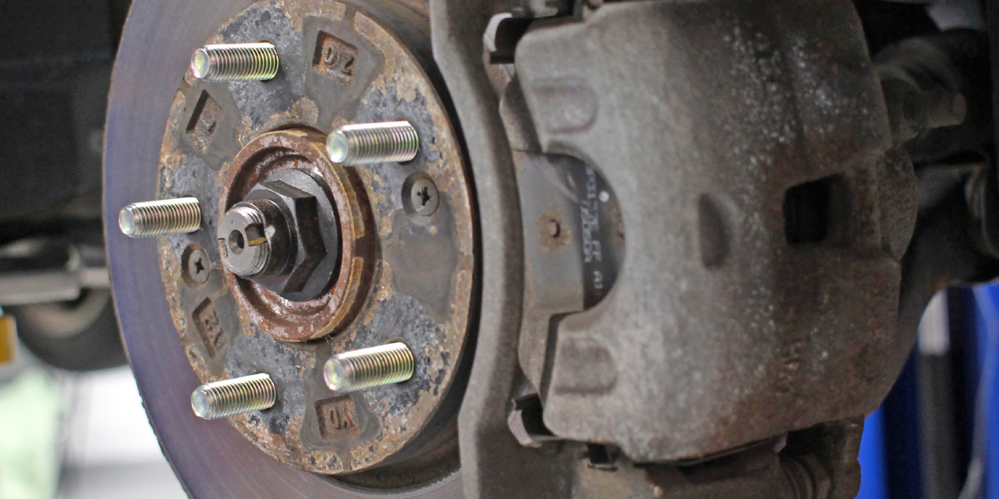
Runout that’s greater than 0.005” (±0.001” depending on the rotor or flange diameter) is a sign that the flange, rotor and/or bearing should be replaced. The needle of the dial indicator should be perpendicular to the rotor. Measurements should be taken a quarter inch from the edge.
Flange runout can be corrected with tapered shims to address a runout of 0.003” (0.075 mm) to 0.009” (0.230 mm). A runout of more than 0.005” (0.125 mm) at the bearing flange cannot be corrected by the use of a shim. The combination of rotor and bearing flange could prevent the rotor from being turned. You should check bearing flange runout after friction surface runout. This can be done by changing the rotor position 180º on the bearing. If the high spot changes 180º, the rotor could be Ok or ready to turn after the bearing is shimmed.
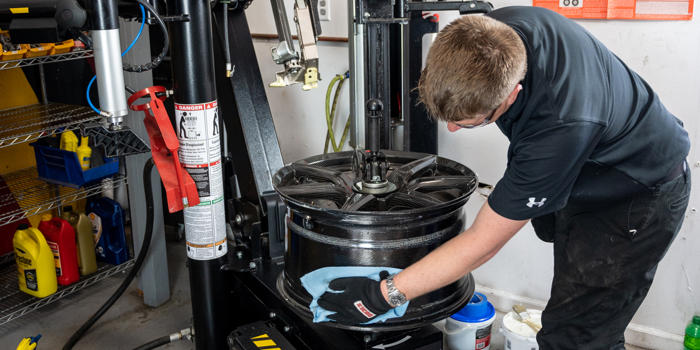
PRODUCTIVITY
Cutting a rotor in one pass is essential for productivity. For non-composite rotors, it is possible to take as much as 0.020” per side while still having an acceptable finish. However, with a composite rotor or one with hard spots, the depth should be reduced, likely below 0.010” per side for a quality finish. In order to remove this much material, it is essential to have sharp bits.
Cutting too fast will reduce the cut quality and possibly create chatter. A larger diameter rotor will need to turn slower than a small diameter one.
Single-speed lathes are set at the slower speed of the largest application they are designed to cut. This is usually around 0.002” per revolution.
When machining a rotor, you have two primary goals: provide a smooth surface finish for the pads and provide a true surface finish. Poor rotor finish can lead to noise. Never use the ballpoint pen measurement method when machining rotors. The only real way to measure is with a profilometer that measures the roughness average. But this tool is very expensive and very fragile. The best way to make sure a lathe is cutting rotors the right way is to make sure your cutting bits are fresh, adapters are true and the crossfeed is set properly.
This article is courtesy of Brake & Front End.