On a mechanical level, it is easy to understand how brakes work. We all understand that brake fluid transfers force from one hydraulic component to another. But, how does this apply to how a brake pedal feels? This is where math is required.
You need only two simple math equations to commit to memory. First, the equation for calculating the surface area of a circle (caliper or master cylinder piston) is Pi or π (3.14) times the radius squared. Second, pressure is equal to the force divided by the area or pounds per square inch. The rest of the math is just multiplication, division and addition/subtraction.
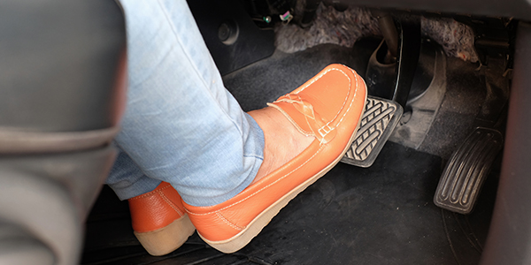
Let’s start with the driver. In a sitting position, the average driver can comfortably generate 70 lbs. of force on the rubber pad at the end of the brake pedal. The brake pedal is nothing more than a mechanical lever that amplifies the force of the driver. This is where the pedal ratio comes into play.
Pedal ratio is the overall pedal length or distance from the pedal pivot to the center of the pedal pad, divided by the distance from the pivot point to where the push rod connects.
The optimal pedal ratio is 6.2:1 on a disc/drum vehicle without vacuum or another assist method. This means that the 70 lbs. the driver has applied is now amplified to 434 lbs. (6.2 x 70 lbs.) of output force. The problem is that the travel of the pedal is rather long due to the placement pivot point and master cylinder connection.
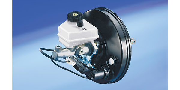
Brake Boosters
A booster increases the force of the pedal so a lower mechanical pedal ratio can be used. A lower ratio can give shortened pedal travel and better modulation. Most vacuum-boosted vehicles will have a 3.2:1 to 4:1 mechanical pedal ratio.
The size of the booster’s diaphragm and amount of vacuum generated by the engine will determine how much force can be generated. Most engines will generate around -8 psi of vacuum (do not confuse this with inches of HG or Mercury). If a hypothetical booster with a 7-inch diaphragm is subjected to -8 psi of engine vacuum, it will produce more than 300 lbs. of addition force. Here is the math:
π(3.14) X radius (3.5)2 = 38.46 sq/inches of diaphragm surface area X 8 psi (negative pressure becomes positive force) = 307.72 lbs of output force
To keep things simple, let’s return to our manual brake example. The rod coming from the firewall has 434 lbs. of output force. When the force is applied to the back of the master cylinder, the force is transferred into the brake fluid.
The formula for pressure is force divided by the surface area.
If the master cylinder has a 1-inch bore, the piston’s surface area is 0.78 square inches. If you divide the output force of 434 lbs. by the surface area of the piston, you would get 556 psi (434 lbs. divided by 0.78 inches) at the ports of the master cylinder. Not bad for a 70 lbs. of human effort.
If you reduce the surface area of the piston, you will get more pressure. This is because the surface area is smaller, but the output force from the pedal stays the same. If you used a master cylinder with a bore of 0.75 inches, that has a piston with 0.44 inches of piston surface area, you would get 986 psi at the ports for the master cylinder (434 lbs. divided by 0.44 inches).
But, how is this force transferred to the calipers? How does the size of the caliper piston change the force needed to push the brake pad to the rotor?
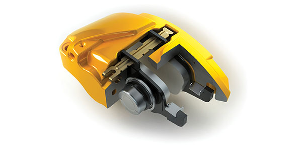
If the calipers are a single-piston floating design with a two-inch diameter pistons (piston surface area = πR2 x 2), we just multiply piston surface area by 556 psi and we get 3,419 lbs. of clamping force at both front calipers!
In our theoretical example above, we are ignoring some real-world factors that influence the amount of clamping force. The reality of it is that not all of the 556 psi makes it to the caliper, and some of the force is wasted flexing the caliper and compressing the brake pads.
While the brake fluid is traveling from the master cylinder to the calipers, it is pushing on the walls of the brake lines and hoses. This means that some of the pressure or pedal effort is lost. This is why engineers try to keep the amount of flexible hose to a minimum. This is also why race cars use braided flexible like to reduce compliance.
Even if all of the pressure makes it to the caliper piston, some of the generated force is lost as the caliper flexes. This flexing can occur at the bridge or mounting points. Most floating-caliper designs can have more flex. Opposed-piston designs are typically stiffer. But, if the input pressure and piston area is the same for both designs, the calipers will generate the same theoretical forces.
If you try to improve a system by changing to larger calipers with more piston surface area, or change the diameter of the master cylinder, you are upsetting the balance.
One of the advantages of four-, six- or even eight-piston calipers is the ability to generate the force more evenly over a larger backing plate.
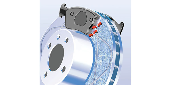
Another factor in the system is the brake pad and how it acts under the force. If the backing plate flexes, braking force is lost as the friction area flexes and changes.
Inexpensive brake pads will often have thinner backing plates as a means to save on steel. This is the leading reason why they can cause a soft or low pedal. It gets even worse if the manufacturer is putting large holes in the backing plate for molding or riveting. Some mechanical attachment designs can eliminate these holes. Another benefit to having a ridged backing plate is less brake noise because the friction surface is more stable and consistent.
The clamping forces are used to generate friction that produces torque to stop the vehicle. This is where “coefficient of friction” comes into play. Basically, the coefficient of friction is calculated by dividing the force required to slide an object over a surface by the weight of the object. For example, if it takes 100 pounds of force to slide a 100-pound brake pad over a rotor, the coefficient of friction between the two materials is 1.0.
Clamping forces and the coefficient of friction are on one side of the equation and brake torque is on the other side. If you increase either variable, you are changing the amount of torque the system can generate.
In essence, engineers balance coefficient of friction with piston and master cylinder sizes to give the vehicle the right amount of stopping force and pedal feel. If you increase or decrease the coefficient of friction, you might be upsetting this balance.
Article courtesy Brake & Front End.