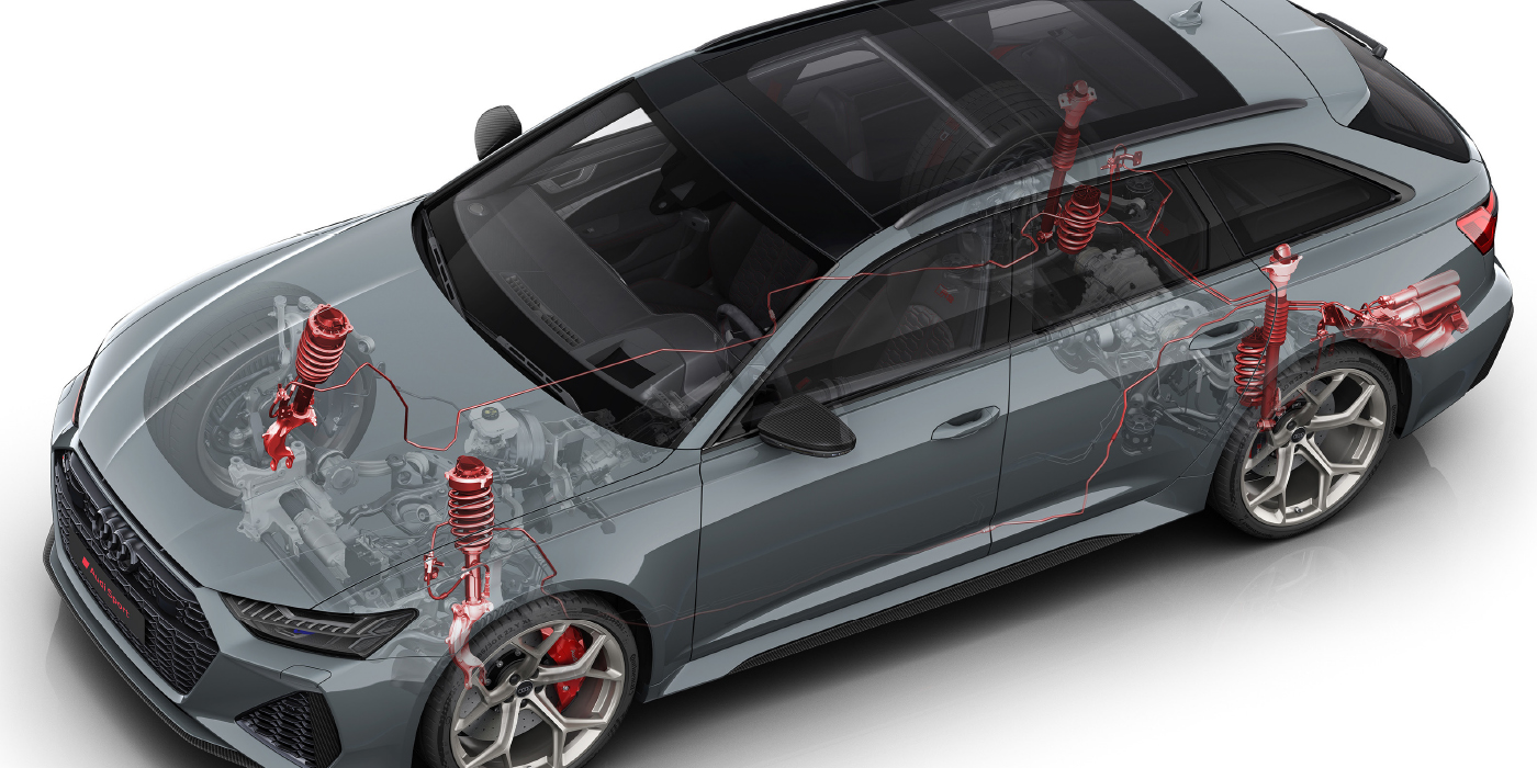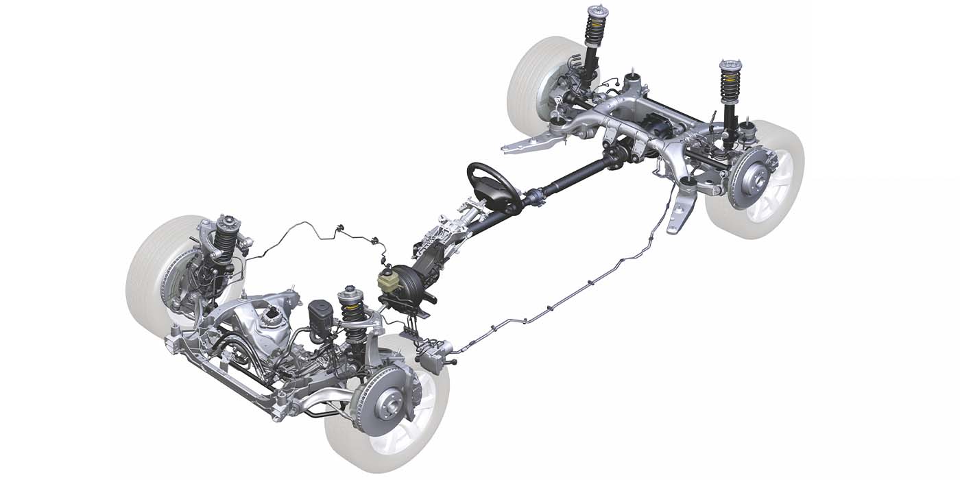
In the 1960s, many domestic and import OEMs replaced kingpins with ball joints. The change helped to reduce maintenance and improve suspension geometry. By the 1970s, finding a light vehicle with kingpins was almost impossible. Today, you can commonly find suspensions with as many as five ball joints on a corner. These multi-link front suspension designs can be found on domestic and import nameplate vehicles from GM, Ford, Audi and Mercedes-Benz.
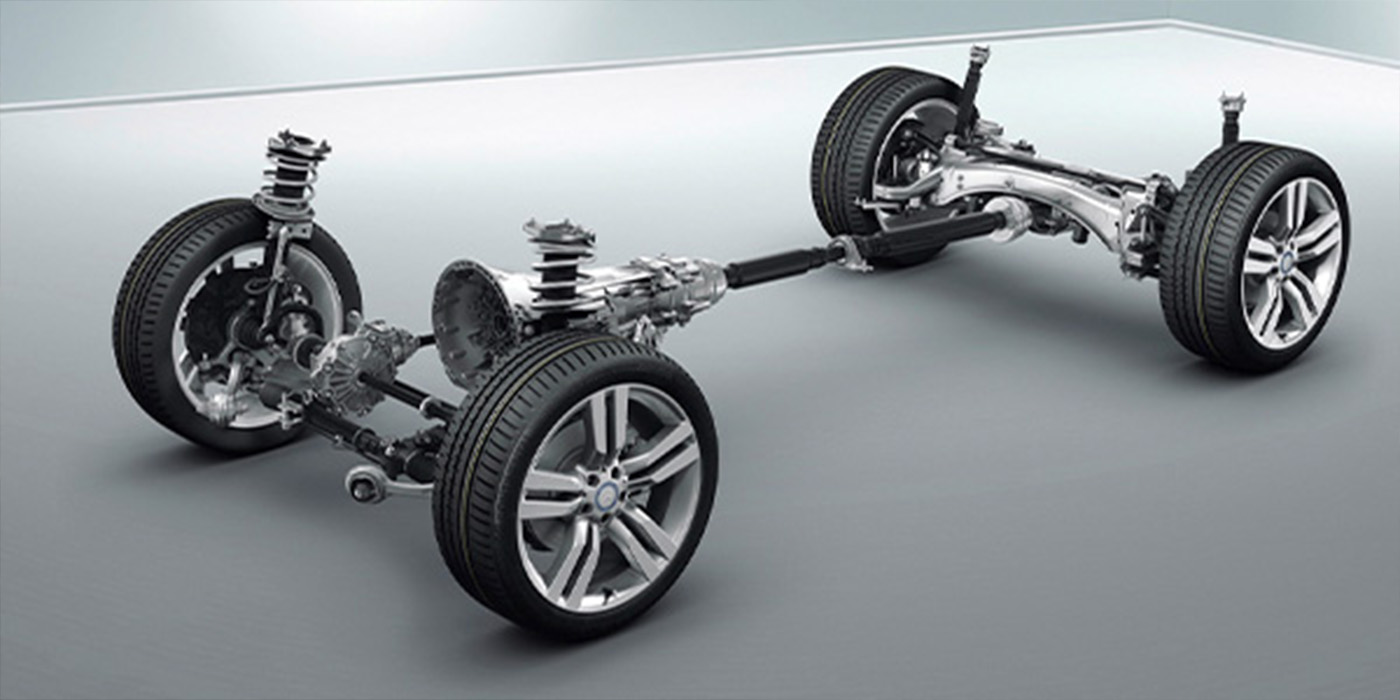
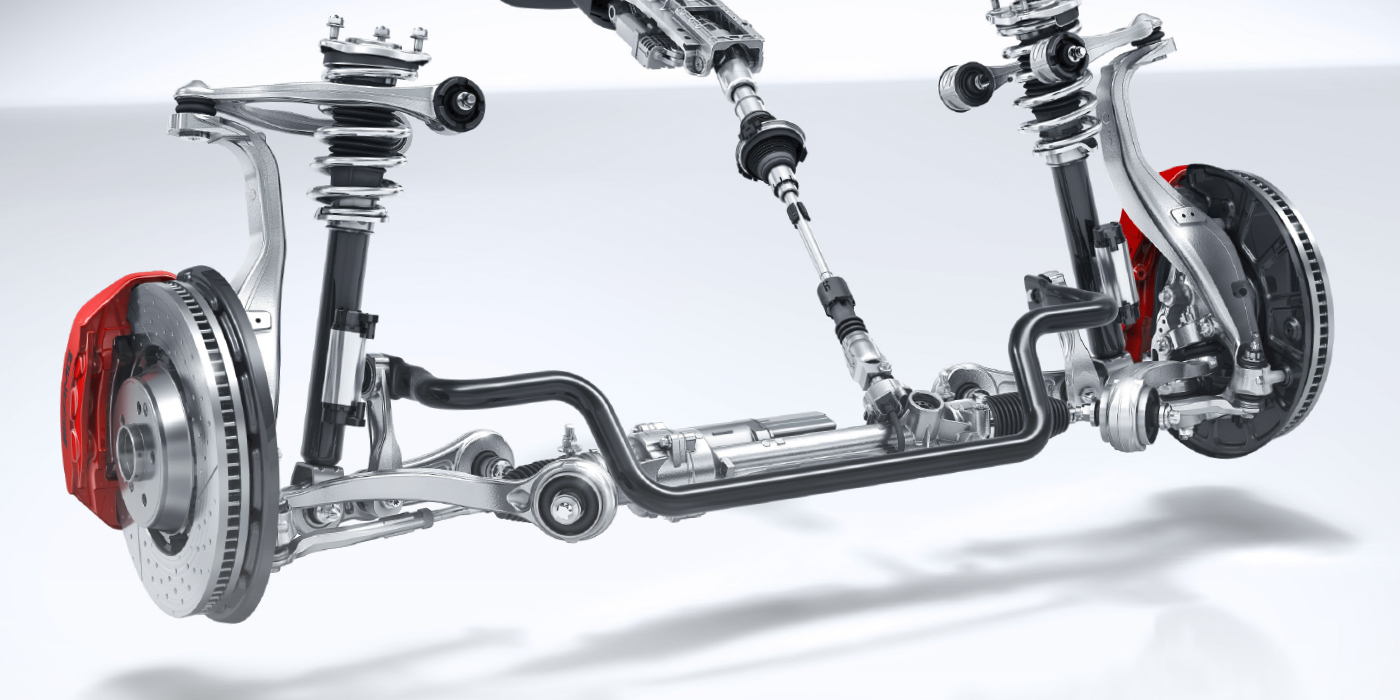
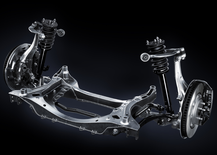
These types of front suspension have two control links in place of an upper or lower control arm. Some suspensions will use just one set of control links in place of an upper or lower control arm. Manufacturers like Audi use an arrangement of four links for both the upper and lower control arms.
Engineers don’t just look at the static angles of the suspension. They look at the dynamic angles as the vehicle corners, brakes and accelerates. They also look at the arc of the suspension links that can pull or push, depending on the link’s height, position and length.
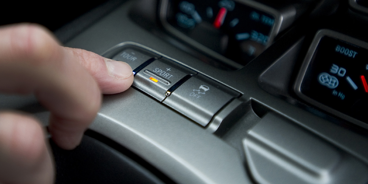
They tune the geometry for optimal ride quality, steering feel and handling.
Need a little extra camber to compensate for body roll and suspension movement? Engineers can do that with suspension geometry. What to improve turn-in performance to a corner? Engineers can do that with toe, scrub radius and geometry. The addition of the extra control arms makes the angles even better.
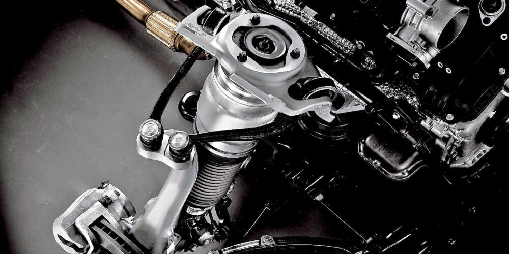
If you look at the upper or lower links and knuckle in a photo, you might think it would be impossible for the steering rack to turn the knuckle attached to two or four ball joints. But with clever geometry and special bushings, the knuckle does turn on an axis between the two arms. The shorter arm with more curve can alter the caster, scrub radius other alignment angles depending on ride height and body movement. These arms move up and down and forward and backward on the bushing. Because the two unequal-length upper arms are mounted to the body at different heights and angles, the geometry is optimized for body, suspension and steering movement.
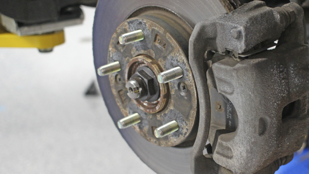
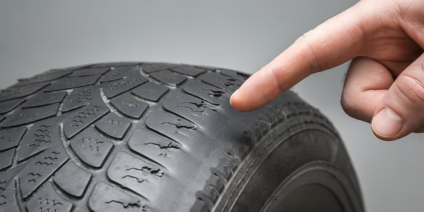
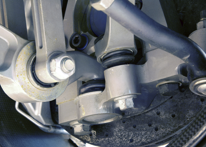
With the control links moving in multiple directions, the stress on bushings can be more damaging. The driver might report tires squealing, altered steering feel and noise. The other symptom is abnormal tire wear. When inspecting the bushings, you might notice torn rubber or separation of the material from the shell or center. If the suspension uses hydraulic bushings, you might see dark stains around the link and bracket. This is because these hydraulic bushings are not filled with petroleum oil. Instead, they are filled with glycol that is closer to antifreeze. This makes it difficult to spot a ruptured bushing.
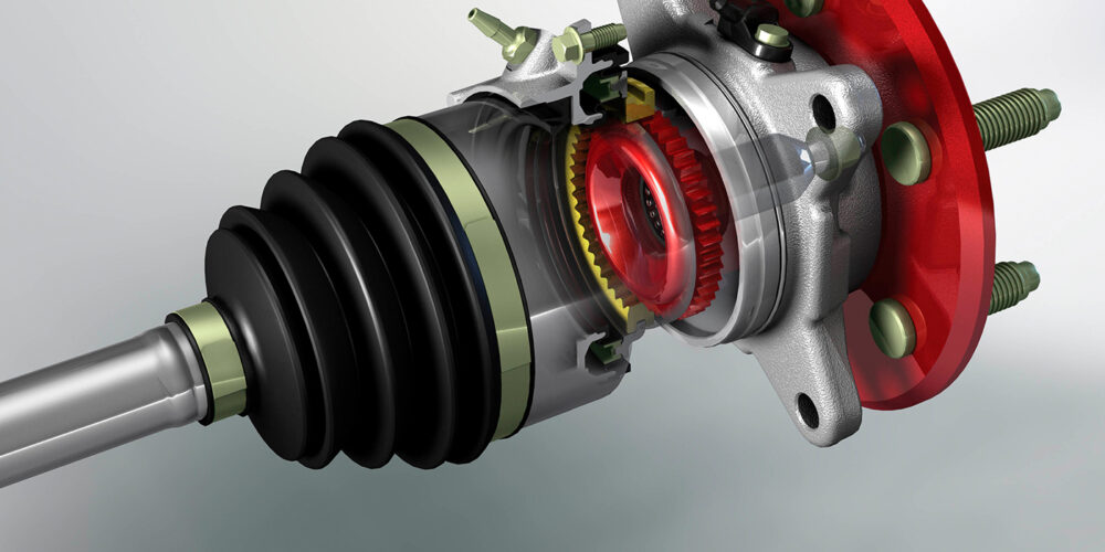
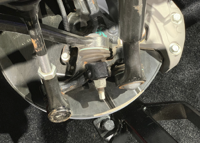
The ball joints can also fail. This will result in noise and play in the suspension. The specification for wear is typically zero movement. Inspect the boots of the joints for any damage.
It is a good practice to replace the links in pairs because a damaged bushing on one link can cause accelerated wear on the bushing on the other link.
Alignment
Aligning these vehicles is similar to other vehicles when taking the initial readings. Looking at the angles, you need to pay attention to the steering included angle. This can often clue you in to possible bushing problems or other damage.
Depending on the suspension design, it might not be adjustable. There are adjustable arms and cam bolts available for some makes and models. When making adjustments, they can create a “cross-talk” between the camber, caster and even toe. Audi recommends “camber balancing” if the specifications are out of alignment. You can purchase adjustable upper links that give ±1.5º of camber and caster. If the camber is out more than 1.5º, check the condition of the bushings on all four arms and look at the cross camber to determine if the cradle has shifted.
If you have any doubts about the adjustments, perform another rolling compensation reading with a full steering sweep.