One of the most difficult problems to cure is an oxygen sensor code related to the heater circuit. If you decide to just put in a new sensor and clear the codes, there is a chance the code will come back because the malfunction in the circuit is not in the oxygen sensor.
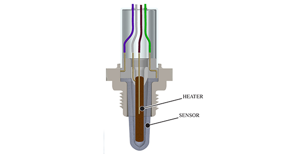
The heater circuit on an oxygen sensor is not a coil of wire wrapped around the ceramic wafer or cone. It is either a layer pressed into the sensor, or it is printed onto the ceramic part of the sensor. Power is applied to the heater and warms the sensor’s elements that detect the difference of oxygen concentrations between the exhaust gases and the reference air in the pump cell. With a faster warmup, the engine can go into closed-loop operation sooner.
There are several types of circuit designs that provide power to the heater. On some older circuits, there will be a fuse and a relay. On some late-model sensors, there is only a module that pulls voltage to ground. But, the majority of systems provide power to the heater with pulse-width-modulated voltage.
Most heater systems test the circuit with a bias voltage. This checks the condition of the circuit before the pulse-width-modulated power is applied. If the engine control module detects an open, short or resistance that is higher or lower than expected, the system will go into a failsafe mode and won’t send power to the heater of the sensor.
Freeze-Frame Clues
Many manufacturers use generic OBDII codes for the heater that start as P0XXX. Some manufacturers will use proprietary codes for the performance of the heater and circuit. But, the one thing the codes share is the storing of freeze-frame data.
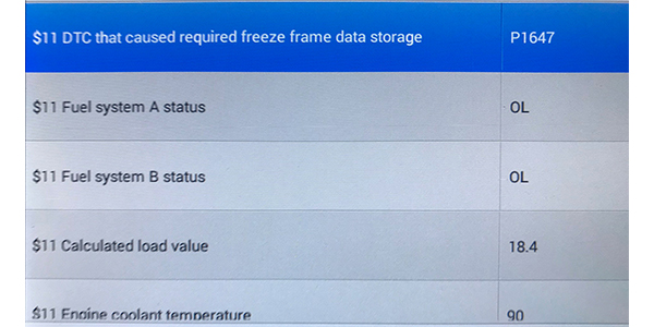
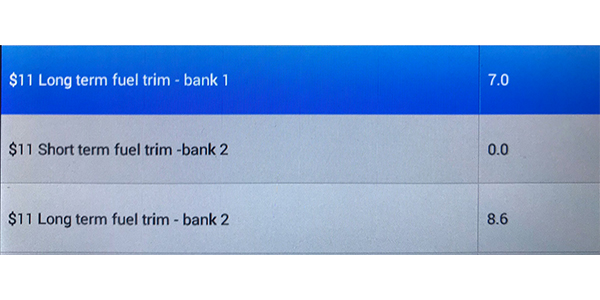
When looking at the freeze-frame data, there are several key pieces of information you need to look for:
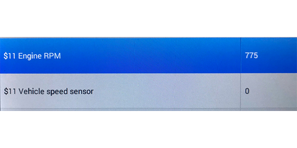
• What was the vehicle doing when the code was set?
• What was the coolant temperature and fuel system status?
• Did the problem occur at idle or under load, and at what rpm?
• What are the fuel trims, and what are the differences between the short- and long-term?
With the freeze-frame data, you can see if the code is set during startup when the coolant is cold and the fuel system is in open-loop operation. Chances are the code will set when the engine is at idle.
Circuit Checks
The easiest check is to measure the resistance between the two terminals for the heater in the oxygen sensor’s connector. The resistance can range from 10-25 ohms, but check the specs. If it is open or has low resistance, it is probably the sensor. But, check to see if a bias-voltage signal is sent or a pulse-width modulated signal is present after the code is cleared. In some cases, you can use a load like a turn signal bulb to see if the pulse-width-modulated circuit is working.
Article courtesy Brake & Front End.