Before we get into this month’s Diagnostic Dilemma, let’s review some points about diagnosing battery drains. As a general rule, a “parasitic drain” of less than 30 milliamps (mA) is normal for most vehicles 15 years old and newer. Keeping in mind that most manufacturers now publish parasitic drain values, let’s assume that a battery drain exceeding 50 mA is cause for concern.
1. “Doing the math” will help define the type of battery drain we’re dealing with. If a fully charged automotive starter battery rated at 60 amp-hours is subjected to a constant drain of about .250 amps or 250 milliamperes (mA), it would take ten days to drain the battery to a threshold value of 10.5 volts. But, if it’s an intermittent drain caused by sticking relay contacts or a sticky door latch position sensor, that rule won’t apply.
2. “Old School” testing methods are counter-productive to accurately measuring, estimating, and locating battery drains on modern vehicles.
3. Diagnosing any modern networked system with multiple modules requires an accurate low-amperage current probe and adequate service information.
4. Using a conventional battery charger to boost a discharged or defective battery won’t produce the stable voltage values needed for voltage drop testing.
5. A power distribution chart provides a better illustration of power flow than a wiring schematic to help trace a battery drain.
6. Opening a hood or door on a modern vehicle can “wake up” multiple modules in the networking system. The operative words here are, “non-invasive.”
My current method is to leave the hood up, the windows rolled down, and the ignition keys on the front seat 24 hours before testing. This allows all modules to time out and remain “asleep.” So let’s solve this month’s Diagnostic Dilemma by working through a more advanced level of parasitic battery drain diagnosis on two case-study vehicles, a 2000 Jeep Grand Cherokee with a battery drain and a similar 1998 Grand Cherokee with a module drain.
COVERING THE BASICS

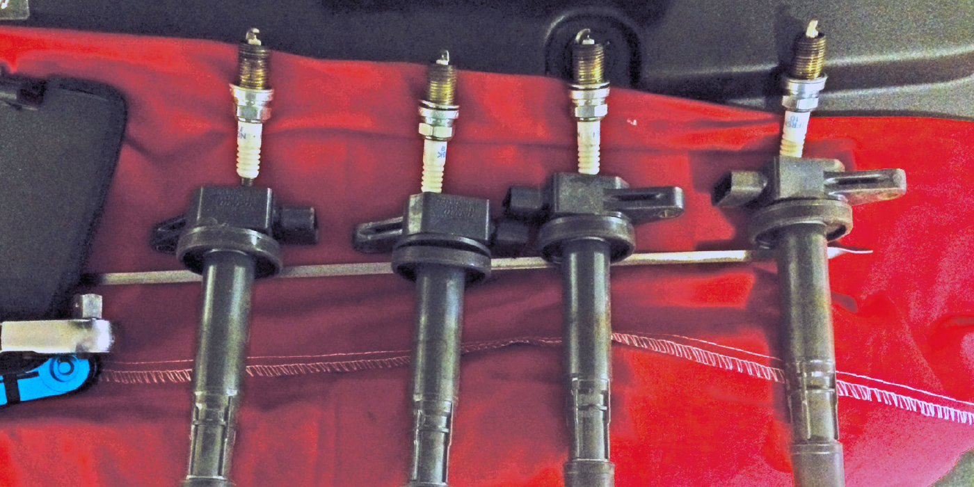
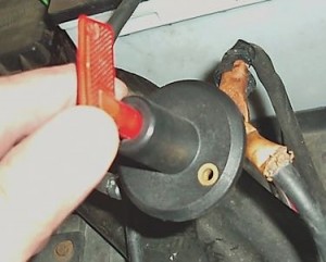
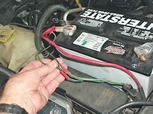
Our first case study is a 2000 Grand Cherokee (Photo 1), that was draining the battery so quickly that the original do-it yourself owner had installed a master switch to disconnect the battery (Photo 2). The Jeep was then sold to a second party, who didn’t realize the complexities involved with solving this battery drain problem.
My client shop quickly recognized that the high-amp sound system installed in the Jeep was likely causing the high-amperage battery drain and, with the current owner’s permission, removed the system. The shop then determined that a low-amperage battery drain remained, which they couldn’t locate. I advised the shop to save diagnostic time by testing and fully recharging the battery. If the battery didn’t pass a conductance test, a known-good battery was to be substituted to provide a stable system voltage. The shop also left the hood up, front windows rolled down, and the ignition key on the front seat as requested, which avoids the issue of wasting even more diagnostic time by waiting for the on-board modules to time out.
RED FLAGS
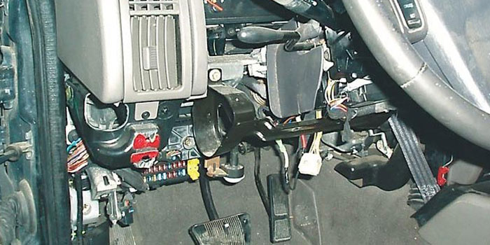
The Jeep was parked in the shop overnight to time out the modules. The next morning, the battery drain tested at 240-250 milliamperes (mA). The 200-300 mA-range far exceeds the permissible 30-50 mA range and appears frequently when an aftermarket accessory is involved. But more alarming was the “crisp” wiring leading from the main harness to the under hood fuse box and two badly burned alternator field control wires leading from the PCM to the alternator (Photo 3).
Burned wiring is always red flag because the cost of replacing a main wiring harness can be prohibitive on newer vehicles and nearly impossible with older vehicles because a replacement wiring harness is no longer available.
In this situation, the harness must be removed, opened, and repaired, which is a labor-intensive job that might exceed the vehicle’s market value. Thankfully, the burned condition was limited to wires dropping outside the main harness. With the integrity of the harness now established, we set about locating the battery drain.
CHASING THE FAULT
Since an active relay is warm to the touch, my first step was to check each relay for warmth. All felt cool to the touch, so I used a low-amp probe to trace the drain through the cable connecting battery positive to the under hood fuse box. Since voltage-drop testing indicated no current flow through the mini-fuses and since cartridge fuses can’t be tested by voltage-dropping, I was forced to remove cartridge fuse #7, which reduced the battery drain to nearly zero amps. According to the power distribution chart, fuse #7 supplies the interior fuse block located under the dash.
When fuse #7 was reinstalled, the battery drain increased to 350 mA, which meant that a module was now timing out. Not a problem because I knew that my original parasitic drain remained at 240-250 mA. While measuring the voltage drop across each of the interior “junction block” mini-fuses, I located a voltage drop across mini-fuse #23.
According to the power distribution chart, mini-fuse #23’s only function was to power the brake light switch. At this point, I recommended to the shop owner that they replace the burned alternator wiring and determine why the brake light switch B+ wire was drawing 250 mA.
Once into the lower dash, they discovered a badly burned aftermarket wiring harness connected to the B+ wire on the brake light switch. Not wanting to spend a day removing the whole dash, the shop simply cut the wire out of the harness and started the engine.
SURPRISE, SURPRISE

With the engine running, the instrument cluster quit displaying data. The real Diagnostic Dilemma occurred when the cluster began displaying data after the alternator field was disconnected. My client shop believed that the PCM was defective. While I readily acknowledged that possibility, I wanted to confirm that by checking the mechanical instrument cluster wiring schematic. Pin #10 at the cluster connects to the Programmable Communications Interface (PCI), which allows the PCM to share the coolant temperature, oil pressure, charging voltage, tachometer, speedometer, and fuel level data with the instrument cluster. None of these gauges would work with the alternator field connected.
To solve the second part of this Diagnostic Dilemma, let’s return to the two burned field control wires at the alternator. A wiring schematic indicates that “Gen Source” (PCM pin #25, connector #3) and “GEN Field Driver” (PCM #10 connector #2) lead to the brush assembly at the alternator. Apparent logic leads to a diagnostic scenario in which the alternator field circuit amperage increased to far more than needed for normal electrical loads (shorted rotor?). Because the PCI and “Gen Source” circuits are in close proximity to each other at connector #2, it’s reasonable to suggest that an overheated B+ alternator field driver would short the PCI circuit to voltage or ground inside the PCM when the alternator field was connected.
My client shop had previously pulled code P1687 (no cluster bus message). The OE diagnostic for P1687 suggests inspecting the wiring for pushed-out terminals and broken, pinched, or connectivity problems. That already done, we elected to replace the PCM, which solved the Mysterious Instrument Cluster Disconnect problem.
MODULES AND BATTERY DRAIN
Let’s look at a brief diagnostic history of a module draining the battery on our second case study, which again is a 1998 Jeep Grand Cherokee that happens to be owned by the same person as our first case study. The battery negative-to-engine cable displayed nearly zero milliamperes (mA) current flow while the battery negative-to-body ground wire displayed exactly 200 mA.
Using the voltage drop method, I detected current flow through the 50-amp maxi fuse labelled “MUX-Tow.” Unfortunately, the power distribution chart indicated two 50-amp fuses, with one supplying B+ to the “MUX-Tow” and the other to the Controller Anti-Lock Braking (CAB) module. This discrepancy, along with an error in the component location chart, temporarily led me to suspect bad CAB module.
Nevertheless, a direct measurement across the fuse pins at the single available 50-amp maxi-fuse yielded a 180 mA drain, which is typical of a small bulb or active module. When I added a normal 20 mA parasitic drain to 180 mA battery drain at the 50-amp maxi-fuse, it equaled the 200 mA indicated at the body-to-battery negative ground wire.
Digging further into the power distribution chart, I found that the MUX-Tow fuse supplies B+ to 20-amp fuse #7 inside the passenger compartment fuse box, which then supplies B+ power to the Body Control Module (BCM). Removing fuse #7 eliminated the 180 mA drain. Going a step further, disconnecting the BCM eliminated the battery drain. After verifying ignition switch operation, I’m ready to recommend replacing the BCM.
When discussing body control electronics, it’s important to understand that before 2004 when Controller Authority Network (CAN) technology was introduced to the domestic market, most domestic vehicles were using a very simple body control topology (configuration) consisting of a high and low-speed data transmission system. It’s also important to note that body control bus systems are very application-specific. So for our purposes, I’ll address the Chrysler CCD and SCI bus systems found in this 1998 Grand Cherokee.
OPERATING STRATEGIES
Since most of the detailed service information on this system was delivered in a live classroom, I’ll have to make an educated guess on the operating strategy for this 1998 Jeep. A wiring schematic provides the best source for “reverse engineering” the components activated by the BCM.
1) The BCM must be powered at all times so when it senses an “open” signal from the door and hatch sensor switches, it will activate the interior lights.
2) The BCM is looking for a key-on signal so it can “wake up” other modules and activate components required for actually driving the vehicle. I’ll also mention in passing that many vehicles are equipped with battery saver modules that are capable of timing-out the interior lights and other accessories after the ignition is turned off. As a general statement, if the battery is completely drained, the battery-saver system isn’t working or the electrical system has been modified.
But can a module drain a battery by “waking up” during the night? The answer is “yes” because many years ago, I experienced problems with the old ‘90s-era Chrysler body control modules (BCMs) “waking up” at night, presumably in response to changes in ambient temperature and humidity. The common symptoms were windshield wipers parking vertically on the windshield or the trunk lid popping open during the night. In one memorable case, the BCM would activate the HVAC blower motor and drain the battery. But these were no-code pattern failures and easily solved by replacing the body control module.
To detect intermittent overnight battery drains, I have used a multimeter with a 24-hour time base coupled with a low-amp probe on min/max to detect a module waking up and increasing normal parasitic battery drain. A scope/graphing multimeter can be used for the same purpose. But keep in mind that the testing should be done outside to expose the modules to changes in ambient temperature and humidity.
As on-board diagnostics improve, some OE and aftermarket scan tools will be able to detect an unauthorized module activation, which vastly improves the odds of detecting a random battery drain. Whatever the situation, intermittent and random battery drains will continue to pose Diagnostic Dilemmas for many current and future diagnostic technicians.
Article courtesy Underhood Service.