 As the saying goes: “The devil is in the details.” Another saying is: “The truth is in the numbers.” When performing a brake inspection, both are true. Replacing the calipers and rotors with every brake job may not be the cure all for ending all fundamental brake repair problems. An inspection of every component, from the pedal to the wheel bearings, is the only way to get the complete picture. Documenting the information from the inspection can give you the confidence that you did everything right. A dial indicator, caliper, pin anvil micrometer straight edge and feeler gauge are the tools required, plus the time for the inspection.
AFTER FURTHER REVIEW…
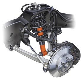
Inspection of the rotor to the bearing flange and wheel to rotor flange is very important. Some bearings have two mounting flanges. One to the knuckle or suspension and the other for the rotor and wheel. Both are machined surfaces to align the rotor to the caliper. The mating surfaces for these flanges must be true and free from damage and debris. This also applies to the mounting flanges.
 The bearing and mounting flange should be inspected prior to replacement or turning a rotor. The bearing should be inspected for end play at the flange. The wheel studs should also be inspected. This is especially important if the rotor is to be turned on the vehicle.
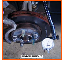
The mounting surface of the rotor to the bearing flange should be inspected for damage and debris that could affect its mounting to the bearing flange. It is important that these machined surfaces mate without any type of distortion. There could be a case where the bearing flange could have runout and the rotor not have the runout. Runout is checked using a dial indicator.
The setup is the same as checking for end play with the contact point of the dial indicator at the outside and perpendicular to the flange. The flange is rotated to measure the runout. A lateral runout of 0.005 inch (0.13 mm) could produce as much as 0.025 to 0.030 inch (0.64 to 0.76 mm) runout at the rotor friction surface. If the bearing is OK, there are brake correcting plates available to fix the runout condition.
T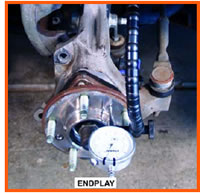 he mounting surface of the rotor to the wheel should be inspected for damage and debris that could affect the mating of the wheel to the rotor. The mounting surface for the wheel should also be inspected for damage and debris. This is especially important with a cast aluminum wheel. Special attention should be paid to the center pilot hole.
CHECK FOR DAMAGE
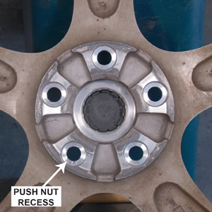
In many cases, corrosion can cause the wheel to seize on the hub. A wire brush attachment for a drill can be used to clean this corrosion from the hub and wheel. The wheel-mounting surface should be checked using a straight edge. Push nuts are used in the assembly of the vehicle to ensure the retention of the rotor. If the recessed areas for the push nuts are not clear, when the wheel and tires are rotated or replaced, it could cause the rotor to warp from the differences in clamping pressure. The mounting surfaces should be flat. Cupping in the center of the mounting surface could cause the rotor to warp.
FRICTION FINDINGS
 The friction surface of the rotor should be inspected for runout, parallelism and surface condition. When deciding whether to turn or replace, the first inspection should the friction surface. The minimum thickness of the rotor is cast or stamped on the mounting flange. A dial caliper can be used to measure the thickness of the rotor. If the rotor is at the minimum thickness, it needs to be replaced.
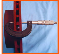
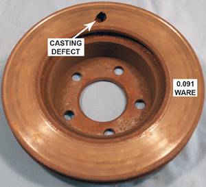
The rotor thickness is greater than the minimum thickness and there is minor scoring. To determine if the rotor finish can be restored, make a visual inspection for heat damage that is indicated by the discoloration of the friction surface. Use a pin anvil micrometer to check the deepest score on each side of the rotor and subtract it from the thickness of the rotor. If the measurement is more than the minimum thickness, the rotor can be turned.
 If the rotor friction surface is smooth and is not discolored, it should be checked for runout. The setup for checking is the same as checking the bearing with the dial indicator contact point at the center and perpendicular to the rotor friction surface. Runout up to 0.10 inch (0.25 mm) is acceptable. Runout up to 0.050 inch (1.27 mm) can be corrected by turning the rotor, provided the rotor meets minimum thickness.
Why go to all of the time and expense to inspect the rotor when a quality repair says the rotors are replaced no matter their condition. Discolored rotors and short pad life could tell you the driver is right foot gas, left foot brake. Warped rotors and new tires could tell you that when the tires were replaced, the wheels were improperly installed. Scored rotors could mean problems with the first brake job.
 Whether you turn the rotors on a lathe or on the vehicle, all of the inspections are worth the time. If you turn the rotors on a lathe it is important to mark the high and low spots. You could have a warped bearing flange and a true rotor. If you turn the rotors on the vehicle, it is important to check the end play of the bearing. Excessive lateral runout could mean a combination of a warped bearing flange and rotor with the rotor that can be machined.
The installation of the wheel is the most important operation. The proper procedure and torque of the lug nuts or wheel bolts insures that the rotors will not warp; the stops will be smooth and quiet.
Did You Know…
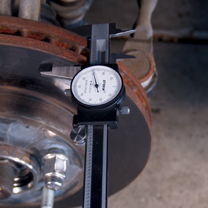
 The brake inspection is performed using a dial indicator. The indicator is mounted to the knuckle or suspension and the indicator contact point on the flange. It is important that the contact point be perpendicular to the bearing flange. A push and pull pressure should be applied to the flange to check for end play. More than 0.004 inch (0.11 mm) end play is an indication that the bearing should be replaced.
 Did You Know…
Parallelism is measured by the thickness of the rotor at a minimum of four locations 90º apart. Any variation in thickness indicates the rotor needs to be replaced.