
Today’s modern internal combustion engine is more regulated by state and federal government than ever before. As environmental regulations get tighter, the need for more precise control over tailpipe emissions has become greater. Modern technology has allowed us to more closely monitor the byproducts of combustion by introducing new components that can more accurately determine fuel delivery at any given moment, resulting in a more efficient and complete burn. Air/fuel ratio (AFR) sensors have largely taken on this role and have become commonplace in today’s automobiles, taking over where traditional O2 sensors have left off.
Are O2 sensors being replaced by AFR sensors because they’re not smart enough?
Not exactly. It’s more like they are being replaced because they are partially “blind.” One major limitation that O2 sensors have is that they were designed to detect only the presence of unburned oxygen, not unburned fuel. It only knows if there is too much or too little oxygen in the exhaust stream. Since it was not designed to detect fuel, it can only “see” half of the air fuel ratio. This is precisely why an O2 sensor is only capable of sending rich, lean or stoichiometric signals to the computer, as opposed to precise air/fuel ratios.
How Do O2 Sensors Work?
Zirconia-based O2 sensors utilize an operating voltage range between 0.100 and 0.900 volts (100mV– 900mV). It is widely recognized that a signal of 450mV reflects a stoichiometric air/fuel ratio of 14.7:1. It is also widely recognized that maintaining a constant 450mV signal from the O2 sensor is impossible due to the rapidly changing conditions to which the engine must adapt (engine load, RPM, temperature, atmospheric conditions, etc.). So, if the computer sees a voltage signal of MORE than 450mV, it recognizes a rich condition, and begins to subtract fuel until it reaches 450mV. If the computer sees a voltage of LESS than 450mV, it recognizes a lean condition, and begins to add fuel until it again reaches 450mV. This is precisely why the upstream (pre catalytic converter) O2 waveform trace looks like a fairly consistent AC sine wave that fluctuates rhythmically between rich (900mV) and lean (100mV). It does this in an attempt to average 450mV, thus achieving stoichiometry.
To better understand the simplistic nature of an O2 sensors operation, I offer this analogy. Imagine having to put a single book in a precise location on a long shelf that contained hundreds of other books while being blindfolded. The only help a friend could offer is to tell you “left” or “right” without expressing how close you were, until you were only one book away from your target location. Once you have arrived at the correct location, your friend would abruptly yell “bullseye!” At no time during the process did you know how far away you were from the target location; you only knew when you had hit your mark. The way you were told “right” and “left” by your friend, is the same way an O2 sensor tells the PCM “rich” or “lean.”
‘Narrowband’ O2 sensors
Traditional zirconia O2 sensors are sometimes referred to as narrowband O2 sensors due to their “narrow” field of view when looking at a vehicles status of either being rich or lean. By design, they report only a rich or lean mixture as it approaches stoichiometry, rather than looking at the entire process of how it got there. For example, imagine watching a NASCAR race by looking only at one “narrow” part of the track. The racecars would enter and exit your view very quickly. Although you would be able to identify the cars as they pass, you would not understand the context of why or how it happened since you were not able to see the entire racetrack.
Enter Air Fuel Ratio Sensors
The industry has begun to use AFR sensor because it has the ability to “see” a much wider spectrum for fuel delivery, but, more importantly, can determine a precise air/fuel ratio along that spectrum. Since AFR sensors can control fuel delivery more precisely, they are quickly replacing upstream (pre catalytic converter) O2 sensors in many vehicles. Traditional O2 sensors are still being used as downstream (post catalytic converter) since their purpose is to verify the function of the upstream sensor (and not to determine actual fuel delivery).
A Picture is Worth a Thousand Words
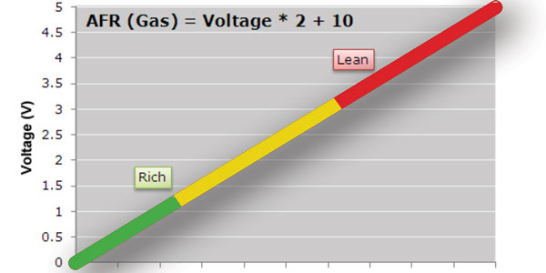
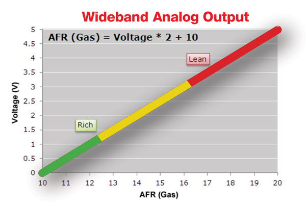
When looking at the wideband analog output (graph 1), you will notice that the output is linear throughout its entire range. Because of this, each point along its output is unique and can be referenced to a specific air/fuel ratio using the mathematical formula (AFR = Voltage x 2 + 10). Try it out for yourself. Pick a voltage on the graph, multiply it by 2, add 10, and you will arrive at a specific air/fuel ratio listed across the bottom. Think of this formula as generating the specific GPS coordinates along the graph for a particular air/fuel ratio!
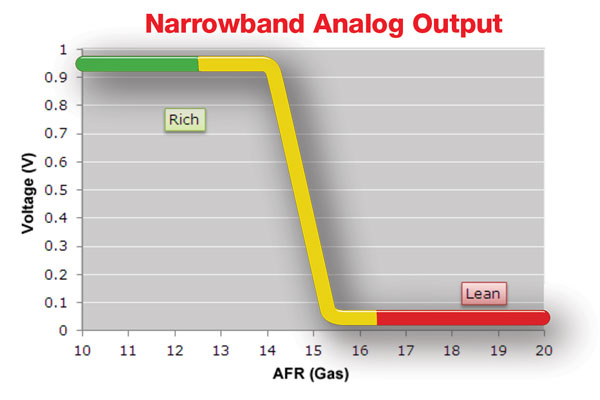
I now direct your attention to the narrowband analog output graph (graph 2) which is representative of a traditional zirconia oxygen sensor. Note that while the engine is running rich, the output voltage does not change until it approaches 14.7:1! Since the voltage does not change, a specific air/fuel ratio cannot be determined like the wideband sensor. Only when the ratio approaches stoichiometry does the voltage begin to vary. The same is true as the air/fuel ratio begins to go lean. Beyond roughly 15.2:1, the voltage output does not vary, again not allowing the fuel monitor to determine the precise ratio. As seen on the graph, an oxygen sensor varies its signal only within a “narrow band” of its entire spectrum, and, for that reason, is referred to as a narrowband oxygen sensor.
How do AFR sensors improve upon traditional O2 sensors?
First, we must understand that traditional O2 sensors change readings by varying their voltage output, while AFR sensors vary very precise amounts of current (amperage). Varying the amperage, instead of voltage, brings both increased precision and complexity. Since current is being varied on the milliamp scale, it is difficult, if not impossible, to use a DVOM for accurate diagnosis. A scan tool is needed to observe an AFR sensors live data, and, therefore, is the recommended tool for diagnostics
Overall, the design and function of an AFR sensor provides the level of accuracy needed to better comply with current emissions standards. To further clarify the precise nature of this type of sensor, I’m returning to my NASCAR analogy. Now, rather than seeing a narrow portion of the track like before, pretend that the AFR sensor represents a wide angle lens on a professional camera, equipped with GPS. You are now able to watch the same race, but, this time, not only do you see the track in its entirety, but you also have the precise location of each vehicle as they circle. Since you have a greater perspective, you now have a greater understanding of the race.
The topic of using AFR sensors to determine fuel delivery is enormous. Diagnostic techniques, application, functional differences, computer interpretations are to name just a few variables that must be explored. Hopefully, you found the information in this article interesting enough to further investigate how the use of AFR sensors help our vehicles remain in compliance with federal and state emission laws. Please feel free to contact me with any questions you may have, or suggestions for further reference material.