It’s All About Doing Your Homework
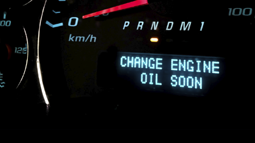
At the amateur end, diagnostics can be about using a code reader to find a diagnostic trouble code (DTC) and a smart phone to find an Internet solution. The Internet solution is fine as far as it goes, but what’s missing is the enable criteria related to the DTC. Without studying enable criteria, we never really learn about why and how a code is stored in the engine control module’s (ECM’s) diagnostic memory, which leads us to changing parts without knowing why.
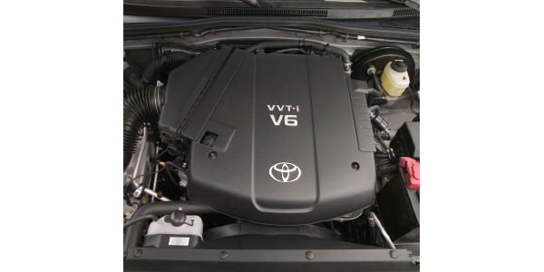
In this month’s Diagnostic Solutions, we’ll explore the world of enable criteria as applied to cooling system DTCs typically found on a 2014 Toyota Tacoma with the 1GR-FE gasoline V6 engine. Let’s begin our discussion of enable criteria by defining “test monitors” and “enable criteria.”
Test Monitors
In brief, the test monitor reads all relevant serial data parameters passing through the ECM. When specific serial data stream parameters from the ECM match the enable criteria, the test monitor generates and stores the applicable DTC in the ECM’s diagnostic memory.
Enable Criteria
Automotive software engineers use a set of data stream parameters that “enable” a diagnostic trouble code (DTC) to be stored in the engine control module’s (ECM’s) diagnostic memory. Enable criteria are normally included with code descriptions found in service information.
As you might suspect, each manufacturer uses its own terminology, such as Toyota’s “Malfunction Detection Conditions.” For our purposes, we’ll stay with the more generic “enable criteria.” That said, the Toyota enable criteria used in this column might differ slightly from aftermarket service information. In any case, let’s begin by examining the cooling system and three DTCs typically found in relation to Toyota Tacoma cooling problems.
Engine Coolant Sensors

Engine coolant temperature (ECT) is a primary data input used for calculating spark advance, idle speed and fuel control. In rare instances, I’ve had faulty ECT sensors cause major no-code drivability complaints on Toyota products. In many cases, the cause of a no-code occurrence can be found by reviewing applicable enable criteria.
Seven different DTCs representing various coolant temperature control problems for a 2014 Toyota Tacoma are listed in my service information. To illustrate how enable criteria can help solve code-related problems, I’ve selected P0115, P0116, and P0128 DTCs to represent an electrical, calibration, and mechanical failure problem respectively on Toyota cooling systems.
P0115 Electrical Description: The engine coolant temperature (ECT) sensor consists of a thermistor that changes electrical resistance in relation to coolant temperature. In short, a 5-volt reference from the ECM flows through the thermistor back to the ECM. As coolant temperature changes, the voltage output changes, which translates into coolant temperature data. The primary trouble areas are the sensor, wiring circuits, and occasionally the ECM.
P0115 Enable Criteria: For the sake of brevity, I’ll paraphrase P0115 enable criteria. P0115 is a “global” or “generic” code that sets when an open or shorted ECT circuit is present, causing the ECM to enter a fail-safe mode with the ECT default value set at 176°F. Related codes like P0117 are set when the ECT circuit is shorted to ground for 0.5 seconds, P0118 is set when the ECT is open-circuit for 0.5 seconds. An open circuit will show a data stream value of -40°F. while a shorted-to-ground circuit will show a value in excess of 275° F. A constant default value of 176° F ECT indicates an open or shorted-to-ground ECT circuit
P0115 Monitor Strategy: Most important, P0115 is a “one-trip” code that sets during the first engine warm-up cycle. P0115 will illuminate the malfunction indictor light (MIL) and can be verified by observing the ECT data stream.
P0116 Calibration Description: The P0116 monitor compares data from the ECT sensor during a cold and warm-start condition to find ECT sensor calibration problems. According to service information. the primary trouble areas include the thermostat or the ECT sensor.
P0116 Enable Criteria: Since P0116 enable criteria is lengthy, I’ll paraphrase or quote Toyota service information as required. P0116 is a DTC indicating a problem with the “Engine Coolant Temperature Circuit Range.” The enable criteria are as follows: 1) During engine warm-up after cold engine start, the change in engine coolant temperature sensor output is below the specified threshold. 2) In duration between warmed engine stopped and next cold engine start, the change in engine coolant temperature sensor output is below threshold.
P0116 Monitor Strategy: Most important, P0116 is a generic “two-trip” code that stores the first failure in “pending” codes. At this point, the MIL is not illuminated. After the second consecutive failure, the test monitor illuminates the MIL and stores a “history” code. If the failure is non-consecutive, it can become an intermittent, no-code drivability complaint. Unfortunately, if the tech erases pending codes, the MIL might not illuminate, leading him to believe that a problem doesn’t exist when in fact it does.
Related sensors: 1) engine coolant temperature sensor, 2) intake air temperature sensor or and mass air flow sensor (MAF). Since the intake air temperature is often contained in the mass air flow sensor, the MAF is considered an essential related sensor. The ECM rationalizes ambient or intake air temperatures by comparing them after an overnight cold-soak. Intake air and coolant temperatures should be essentially equal after a prolonged cold soak.
Typical P0116 Enabling Conditions: 1) Battery voltage 10.5 volts or more. 2) time after engine start: 1 or more seconds. 3) ECT at engine start: less than 140°F. 4) Intake air codes P0112 and P0113 not detected. 5) Engine coolant codes P0115, P0117, P0118 and P0125 not detected. From this point on, the P0116 enable criteria become very detailed, so we’ll move on to DTC P0128.
DTC P0128: P0128 indicates that coolant temperature is below thermostat regulating temperature. The code description is: “This DTC is stored when the engine coolant temperature does not reach 176°F despite sufficient engine warm-up time.” The primary failures are stuck-open thermostats and very low coolant levels.
P0128 Enable Criteria: Enable criteria are: “Conditions (a), (b), and (c) are met for 5 seconds during a 2-trip detection logic.” Condition a) = cold start, condition b) = engine warmed up, condition c) = engine coolant temperature less than 75°C (167°F). The battery voltage must be above 11.0 volts.
P0128 Monitor Description: Required sensors are the ECT, the intake air (IA) and the vehicle speed sensor (VSS). Here again, the ECT and the IA must be functional to allow the ECM to rationalize a sensor calibration problem. Just speculation, but the VSS sensor might be required to sense when the vehicle is moving through ambient air, the better to accurately measure intake air temperatures.
In brief, codes set by variable valve timing, air fuel ratio, mass air flow, intake air temperature, throttle position, engine coolant temperature (ECT), fuel management, misfire monitor, ignition, and vehicle speed sensor (VSS) systems will prevent the P0128 monitor from running. The upshot of this is that if you repair a VVT problem, your customer might be confronted with a bright orange MIL and P0128 thermostat problem the next day.
In addition, the P0128 monitor is very sensitive to ambient air temperatures. Before the P0128 monitor achieves readiness, the cold-start engine coolant and intake air temperature must be more than 5°F or less than 45°F. The warm start engine coolant and intake air temperature must be above 14°F and less than 133°F before the P0128 monitor will run.
It’s All About Doing Your Homework:
If the enable criteria matches the failure pattern, look for the correct code.
1. If we’re looking at an intermittent no-code, cranking no-start, or stalling condition, the CKP sensor is always a prime suspect.
2. Let’s learn how our 2014 Toyota Tacoma detects and categorizes crankshaft position sensor (CKP) failures.
3. Looking at a Toyota Diagnostic Trouble Code chart, P0335 and P0339 CKP codes attract my attention.
4. P0335 is a one-trip code that will illuminate the MIL and set while the engine is cranking or running with no CKP signal present. Likely failure points are the CKP sensor, CKP circuit, or ECM.
5. P0335 appears to be a CKP that stores in the diagnostic memory as soon as the failure occurs.
6. P0339, on the other hand, requires engine speed to be 1,000 or more rpm, starter off, and three seconds or more having elapsed since the starter switch was cycled on/off to detect an engine running, no CKP signal condition.
7. P0339 appears to detect a condition in which the CKP signals intermittently drops out, but not enough to stall the engine.
8. P0339 enable criteria require the CKP signal to be missing for more than 0.05 seconds on a one-trip detection logic.
9. In effect, P0339 is evidently designed to detect missing CKP signals caused by loose connections and broken or frayed wiring, which matches our P0339 enable criteria.
10. Most important, diagnostics can go astray because P0339 is a one-trip code that can set in the diagnostic memory, but not illuminate the MIL.
Doing Your Homework
Enable criteria is a part of modern technology that departs from everyday nut-and-bolt mechanics. Not only do enable criteria explain how trouble codes work, they also introduce us to the world of operating principles and operating strategies. When we learn how an operating system actually works and thinks, we’re well on our way to becoming advanced diagnostic technicians, which is vital to surviving in a world of computer-driven transportation.
–
GARY GOMS is a former educator and shop owner who remains active in the aftermarket service industry. Gary is an ASE-certified Master Automobile Technician (CMAT) and has earned the L1 advanced engine performance certification. He also belongs to the Automotive Service Association (ASA) and the Society of Automotive Engineers (SAE).
Article courtesy ImportCar magazine.