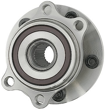
On the hubs for 2005-2014 Subaru Legacy and Outback applications, a speed sensor mounts into the knuckle. It’s exposed end extends out behind the bearing to capture pulses from an encoder ring on the back of the bearing. (The encoder ring is permanently adhered to the wheel bearing outer shell and is not serviceable.)
On the affected vehicles, improper installation of a new hub assembly may cause an ABS, cruise control and/or VDC fault code to occur.
Overview
On the hubs for these applications, a speed sensor mounts into the knuckle. Its exposed end extends out behind the bearing to capture pulses from an encoder ring on the back of the bearing. (The encoder ring is permanently adhered to the wheel bearing outer shell and is not serviceable.)
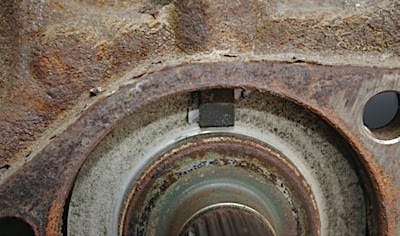
As the wheel rotates, the encoder ring’s small magnetic strips (see Photo 1) create pulses that the speed sensor’s Hall element (see Photo 2) picks up and outputs at a frequency proportional to the wheel speed. Each wheel’s speed signal is transmitted to the ABS and/or VDC module (depending on how the vehicle is equipped), then to the ECM. Cruise control is managed by the ECM. (See Photos 1 and 2.)
On most vehicles, a problem with this speed signal would trigger an ABS code first. It is possible, however, for a speed signal problem to trigger a cruise control fault. Once a cruise control fault is set, it will not re-engage until the ignition switch is cycled (clearing the code).
Any ABS, VDC or cruise control fault code should undergo proper diagnosis to determine the source of the problem, which could be: the speed sensor, sensor air gap, connections, signal interference (radio wave or foreign particles) or the bearing’s magnetic encoder ring.
Inspection Procedure

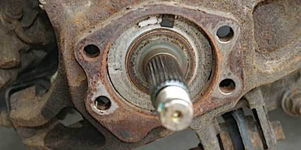
Hub and Speed Sensor Inspection Check for Rust: Any rust present on the mounting area or on the backing plate can keep the bearing assembly from being fully seated (even when it’s torqued down), creating an excessive “air gap” between the encoder and the sensor. It takes only a few extra thousandths of an inch to trigger the false error codes. (See Fig. 1.)
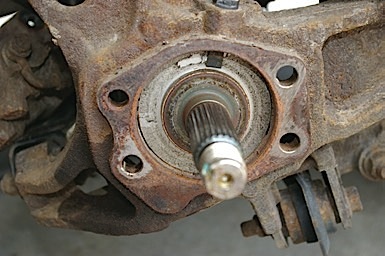
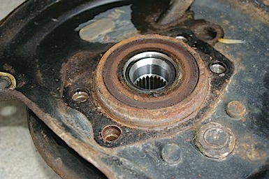
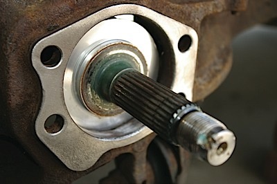
In addition, during reassembly, any rust that’s present on the knuckle or backing plate may be dislodged and will adhere to the magnetic encoder ring of the new hub assembly. Also, check for any dirt, grease or metal particles on the tip of the sensor. Any of these conditions will cause interference within the magnetic field and will result in the pulse being erratic or blocked altogether. (See Photos 3, 4 and 5.)

Installation Procedure
It is imperative that all the components that are involved in reassembly be thoroughly cleaned of rust, scale, grease, dirt and any other contaminants. Using a wire brush attachment, clean the knuckle face. Using an abrasive brush with a rotary tool, clean the inside of the knuckle and backing plate of any loose rust and scale. Follow up with compressed air and brake cleaner spray to clean the knuckle and backing plate surfaces. Once all of the components have been cleaned, follow the factory service manual for hub assembly installation and proper torquing procedure. This vehicle requires the hub assembly to be torqued to 140 ft./lbs. with no load on the hub. (See Photo 6.)
Courtesy of MOOG Problem Solver.