Garbage In, Garbage Out: How to Find It and How to Fix It
The old saying in the computer business is, “garbage in, garbage out.” During the diagnostic process, we occasionally forget that OBD II engine control modules (ECMs) can’t function unless they accurately gather and process data from 5-volt reference sensors. Most engine management sensors are two-wire circuits that contain a 5-volt reference and a signal return wire or three-wire circuits that contain a 5-volt, signal return and auxiliary ground wire.
This month, I’ll use two older case studies including a 1997 Jeep Cherokee Sport and a 2002 Chevy commercial van to provide two real-world examples of how two and three-wire sensors can cause an intermittent rich operating condition.
INPUT, PROCESS, OUTPUT
The foundational concept is simple: a 5-volt reference flows through a sensor containing a resistance that varies according to changes in temperature, pressure or position. Due to this variable resistance, the signal return voltage to the ECM is always less than the reference voltage.
Engine management data like intake air temperature (IAT), engine coolant temperature (ECT), throttle position (TP), mass air flow (MAF), barometric pressure (BARO), oxygen sensor (O2), crankshaft position (CKP), camshaft position (CMP), variable valve timing (VVT), fuel level and other OBD II-related engine sensors are used to control an engine’s spark, fuel and throttle maps. The engine management system can also gather indirect data from the ABS (vehicle speed) and transmission modules (gear range) to help make spark, fuel and throttle position calculations.
The ECM detects sensor failures and sets codes by comparing or “rationalizing” input data among related sensors. For example, data from the coolant, ambient air, battery temperature, engine oil and transmission fluid sensors should be nearly equal following an overnight “cold-soak.” If one sensor is out of range due to faulty calibration, the ECM will set a code for that sensor by comparing it to the remaining three or four data inputs.
The “enabling criteria” for a specific code describes the conditions under which the code will set. In some cases, a sensor might require two drive cycles to illuminate the check engine (CE) light. Other times, the ECM software monitoring a stand-alone sensor might not detect a failure due to the lack of complete data.
When the sensor system is monitoring data correctly, the ECM automatically adjusts the spark and fuel maps and throttle openings to their desired settings. When one or more sensors fail, we begin to see various intermittent and continuous drivability complaints occur. It’s rare, but if a single sensor shorts the 5-volt reference to ground, the ECM might resort to using an engine “limp” mode that drastically reduces power.
TOO RICH, TOO LONG
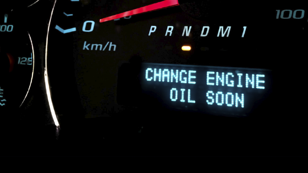
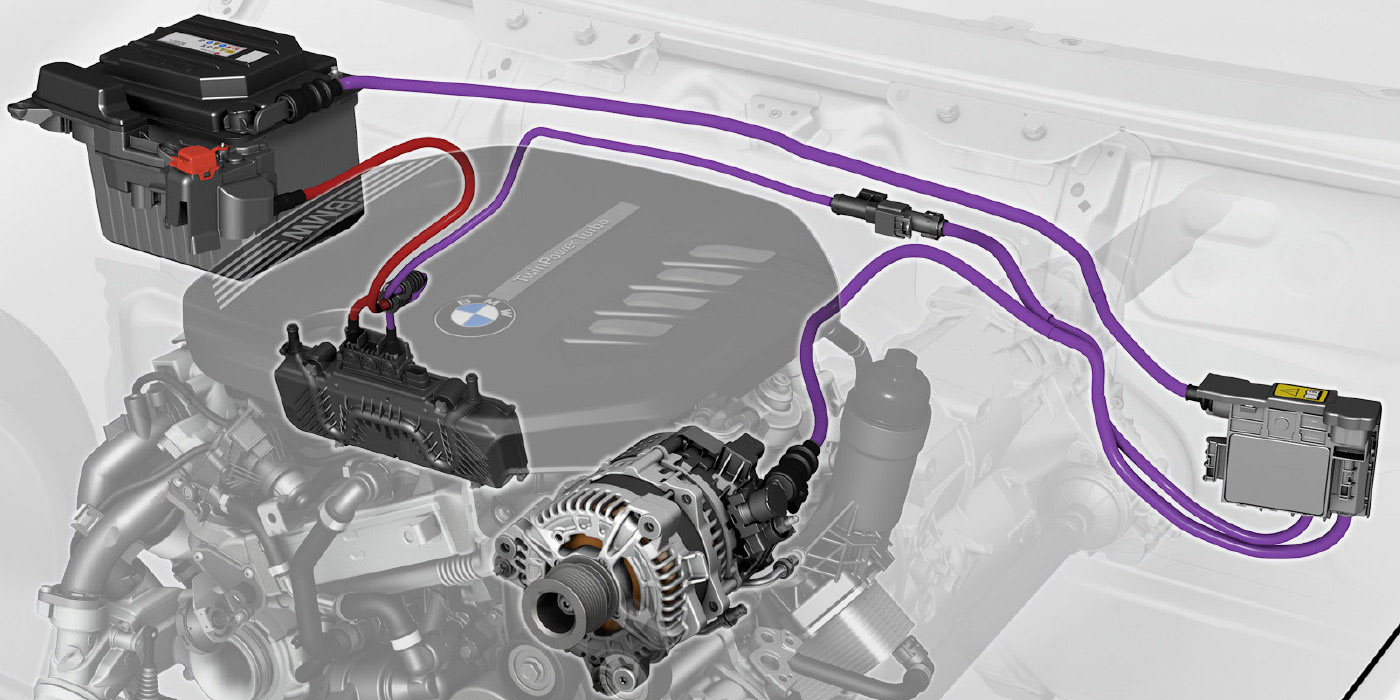
To illustrate a foundational aspect of two-wire sensor diagnostics, let’s look at one of my case studies involving a 1997 Jeep Cherokee Sport with the 4.0-liter engine that was experiencing a stalling complaint about 10 minutes after a cold-soak start (see photo 1). After a 30-minute hot soak, it would run normally.

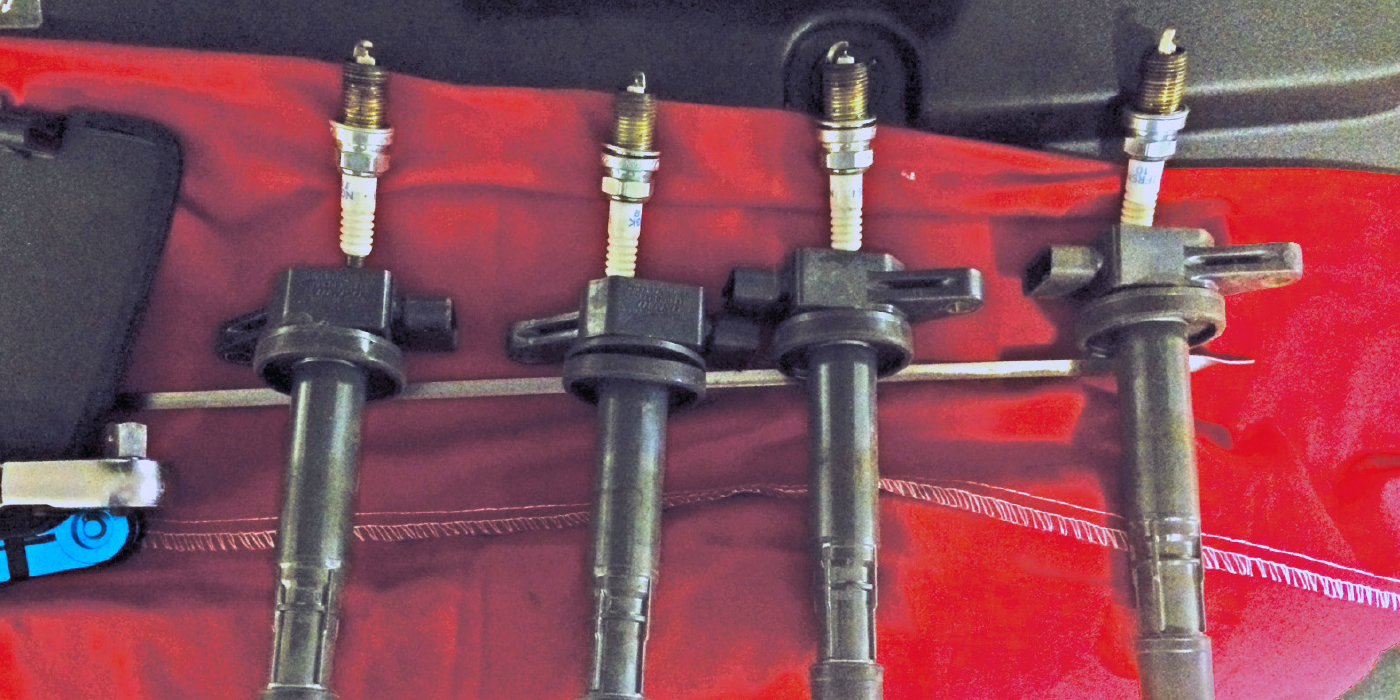
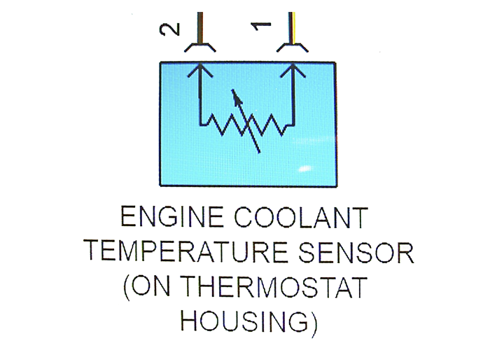
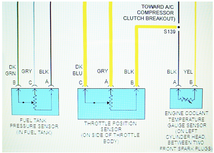
Basic ECT sensor diagnostics include an open circuit displaying -40° F on the ECT data stream and between 250° and 300° F if the reference and signal return wires are shorted together. Out-of-calibration ECTs are detected through the rationalization process. (see photo 2)
As you might suspect, this was a no-code problem that had bewildered two previous shops. If I recall, one shop replaced the idle air control (IAC) and another replaced the oxygen sensor because the exhaust “smelled rich.”
The best practice for diagnosing intermittent drivability complaints is to retrieve and store all relevant codes and data on the scan tool, select the data record or “movie” menu and take the vehicle for a test drive. Analyzing the data stream, it occurred to me that, after about 10 minutes of run time, the engine coolant temperature had barely risen above ambient temperature.
So now we have a garbage-in signal return. Back at the shop, I felt a cold upper radiator hose and saw an empty coolant reservoir. As you might suspect, the ECT sensor was reporting a cold cylinder head that was demanding a rich air/fuel mixture when, in real-time, the smoking hot engine block was demanding a lean air/fuel ratio. This caused the ECM to stall the engine by over-fueling a relatively hot cylinder block.
In most cases, the ECM software should have set a P0128 generic trouble code indicating a stuck-open thermostat and a slow warm-up time. Since this particular model of Jeep evidently doesn’t include a P0128 in its diagnostic menu, I had a no-code complaint.
Due to the engine performing better after a hot soak, the stalling complaint didn’t always repeat after the initial warm-up. After replacing the water pump, I verified the repair by comparing scan tool ECT input data with real-time data from an infrared temperature gun. The air/fuel ratio was hanging around 14.7:1 and the cold stalling problem was solved.
INTERMITTENTLY RICH
Three-wire, five-volt potentiometers are usually grounded to one or more “floating” grounds located inside the ECM. The ECM is then grounded directly to battery negative via the engine block, which eliminates voltage variations among individual sensor ground circuits.
Let’s use another old-school case study to solve a relatively rare problem with a three-wire sensor causing an intermittent loss of power complaint on a 2002 GM 5.7-liter VIN R commercial van owned by a local tourist resort.
I retrieved a P0121 code (throttle position sensor range performance) from the ECM, but at that time, I couldn’t duplicate the complaint. The resort desperately needed the van, so I replaced the throttle position sensor (TPS) hoping that would solve the loss-of-power complaint.
A few days later, the van reappeared, only now the exhaust was pouring black smoke. As for data, the TPS should typically display about 0.8 volts on the TPS signal return at closed-throttle. The TPS closed-throttle data was instead displaying a full 5.0 volts.
Given the 5.0-volt signal return, I would have suspected that the ECM’s software would default to an engine “limp-in” mode. Instead, the ECM’s response to the 5.0-volt signal return was to increase fuel delivery to match wide-open throttle fuel requirements, even at idle speed.
But there’s a software problem with this scenario. Throttle plate travel should range from 0.8 volts at closed throttle to approximately 4.5 volts at wide-open throttle. It’s important to note that software engineers use the 4.5-volt value to rationalize TPS failures.

When the return signal voltage is 5.0 volts, the ECM should have taken into account that the engine is running at idle speed and therefore rationalized that the TPS is either shorted internally or that the reference and signal return wires have shorted together.
But, since the TPS is a three-wire sensor, an open-circuit TPS ground could also be driving signal return voltages high. Knowing that I had perhaps only one chance to locate the problem, I began gently wiggle-testing the TPS ground wire.
About six inches from the TPS connector, the ground wire had broken inside its insulation and instantly made contact and drove the fuel delivery to normal values the moment I touched it. A new TPS pigtail solved the problem.
Article courtesy Underhood Service magazine.