I’m guessing that the term “rabbit hole” originated with Lewis Carroll’s novel, “Alice in Wonderland,” which was first published in 1865. In the opening chapter of this classic children’s novel, Alice is dozing off on a riverbank when she notices a large white rabbit wearing a waistcoat with a large pocket watch in his hand. Alice pursues the rabbit down a long, dark tunnel leading to a nonsensical “wonderland” populated by animals with human personalities. If this tale sounds familiar to the modern diagnostic technician, it’s because most of us have chased our share of diagnostic rabbits down similarly nonsensical rabbit holes.
THE CRANKING, NO-START SEBRING
Fiction aside, this month’s Diagnostic Dilemma begins with a 2004 Dodge Sebring, 2.7-liter VIN R, which ended up in a towing company parking lot after stalling on a rough country road. The owner had recovered codes P0118 (ECT), P0073 (ambient temp), P0122 (throttle position), P0123 (throttle position), P0340 (CMP), P0335 (CKP), P0129 (MAP/Baro) and P0113 (intake air).
The owner also described how, with 200,000 miles on the car, he had the 2.7-liter engine rebuilt by a local machine shop. A few months later, the transmission failed. The car was taken to an out-of-town transmission shop where the transmission was rebuilt, only to experience some unspecified electronic problems that took the shop several months to diagnose and repair. After the repair, some unspecified P0700-series transmission failure codes would occasionally be stored in the PCM. So, now we have a real Wonderland, populated by different types of rabbits with different personalities.
FINDING THE RABBIT
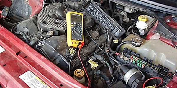
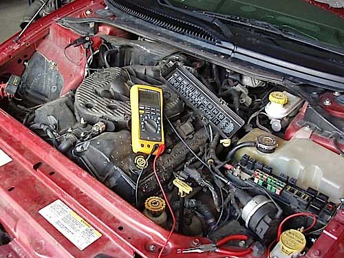
Speaking of diagnostic rabbit holes, I requested that the car not be disturbed until I could diagnose it. After arriving at the towing company parking lot with scope, scan tool and multimeter in hand, I was able to retrieve all the above codes. Although the scan tool communicated with the PCM, no crankshaft position (CKP) sensor or tachometer activity were indicated as I cranked the engine. Since the battery was drained to its last few cranking amps, it was now time to move the Sebring to my shop for a more in-depth analysis. After delivery to my shop, I recharged and tested the battery. The battery didn’t quite meet cold-cranking specification, but its voltage capacity was adequate for preliminary electrical testing.
At this point, a wiring problem was a prime suspect because replacing engines and transmissions can result in the engine harness being stretched or crushed. Stretching the harness can loosen power and ground splices, causing intermittent open circuits. Crushing wires together inside the harness can also cause the voltage to bleed into circuits where it doesn’t belong. Some R&R techs will also forget to tighten grounds or fully connect vital sensors. With the engine key on, engine off (KOEO), I polled all modules and all appeared to be reporting accurate data, so I knew that finding this diagnostic rabbit wasn’t going to be easy.
TP LOGIC
Many technicians fall into a classic rabbit hole by disturbing a wiring harness to locate a wiring problem. Unfortunately, disturbing any wiring harness can temporarily repair the problem. But since the throttle position (TP) sensor is normally accessible on a cable-type throttle, it’s easy to locate suspected wiring harness problems by measuring TP connector voltage. For example, if the TP sensor connector shows no five-volt reference, the reference voltage might be shorted to ground through another sensor or wire.
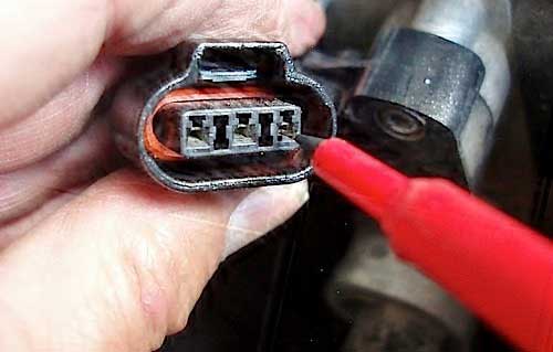
If a voltage drop above 50 mV is measured between the TP ground and battery negative, there’s obviously too much resistance in the ground circuit. As part of its diagnostic strategy, the TP sensor limits signal return voltage to 4.5 volts at wide-open throttle. If the TP signal return shows 5.0 reference volts, the PCM detects an internal short in the TP sensor or that reference voltage is shorted to the signal return wire. So, imagine my surprise when I measured 5.0 volts at each of the three TP connector terminals!
FIVE VOLTS EVERYWHERE
OK, I admit that I’ve never seen 5.0 volts on all three TP connector terminals at once. But there is a logic to this condition. Per the schematic, the TP sensor shares a “floating” ground with the crankshaft position, camshaft position and MAP sensors, terminating at pin #27 in the PCM’s C2 connector. Remember that a “floating” ground flows through the PCM and ultimately grounds to battery negative. Connector C2 pin #29 supplies a five-volt reference for all the above sensors while the TP voltage signal return terminates at pin #21 of connector C2. So, connector C2 is where all the action is taking place. As for the alleged transmission trouble codes, all the transmission control circuits are in connector C4, so I’m going to leave those for later.
But why am I measuring 5.0 volts at all three sensor connector pins when the TP sensor is disconnected? Let’s remember that the TP sensor shows a KOEO, closed-throttle voltage of about .70 volts. Since 5.0 reference volts are present at the TP sensor, the TP’s ground circuit voltage will rise to 5.0 volts if the ground wire is open circuit. Just speculating, but many Chrysler vehicles also incorporate a 5.0 bias voltage from the PCM to detect an open circuit in the TP signal return wire. If so, that’s probably why I’m measuring 5.0 volts at the open-circuit signal return pin with the TP disconnected.
Going back to the original set of trouble codes, let’s note that all the related sensors — P0118 (ECT), P0073 (ambient temp), P0122 (throttle position), P0123 (throttle position), P0340 (CMP), P0335 (CKP), P0129 (MAP/Baro) and P0113 (intake air) — pass through PCM connector C2. Let’s also note that, in contrast to other PCMs, connector C2 contains the PCM’s only five-volt reference source (pin #29) and its only sensor ground (pin #27), which makes this Diagnostic Dilemma even more puzzling. Proceeding with testing, I verified the TP sensor’s voltage readings at all three pins of the camshaft position (CMP) connector, which is located at the top-front of the engine.
COMMON GROUND
Poor grounds can turn relatively simple problems into diagnostic rabbit holes. Not to be confused with the “floating” sensor ground at connector C2 pin #27, the PCM is grounded to the chassis at connector C1, pins #9 and #18 and connector C4 pins #12, #13 and #14. The PCM ground is located at G102 behind the left headlamp.
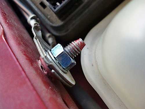
Two ground studs and wires are present, one for the PCM and another for the transmission control relay. I’ve had problems with paint on the stud threads causing bad grounds, so I cleaned both wire loops and ensured a positive connection by installing a .250” external star washer and new nut on each terminal.
WIRE WIGGLING
To avoid falling down another diagnostic rabbit hole, it’s time to start chasing the rabbit by doing a “wiggle” test on the engine harness. One method of doing a wiggle test is to set a multimeter to “min-max” and connect it to the TP connector to provide feedback. A wiring fault will be indicated if the multimeter captures a high or low signal. Another method is to use a scan tool to graph signal return voltages as the wiring harness is wiggle tested. Since I already had my multimeter tapped into the TP connector, I used that method.
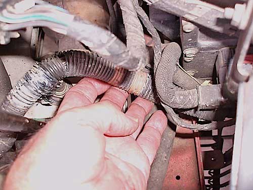
The most important technique when wiggle testing is to duplicate the range of engine vibration and torque movement on the harness. In the case of the cranking, no-start Sebring, it didn’t take but a moment to hear several relays in the underhood fuse box begin clicking as the engine harness was moved. From that point, the diagnosis was a no-brainer.
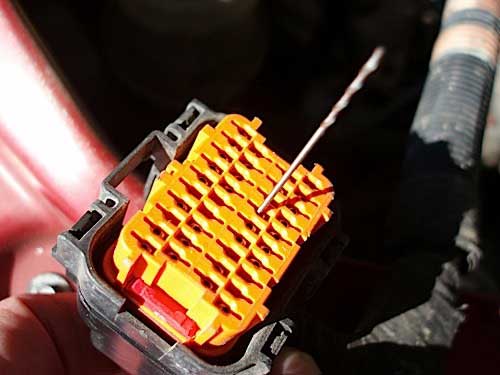
After gaining access to the PCM, I discovered that the plastic locking tab on the C2 connector was broken. This allowed the C2 connector to work loose, which in turn, allowed the ECT, IAC, TP, CMP, CKP, MAP/Baro and intake air sensors to momentarily lose contact. To complicate matters, the remaining pins maintained contact. That experience nearly led my diagnosis down the well-known rabbit hole of believing that no such thing was possible.
My last step was to clean the C2 connector and PCM pins with electrical cleaner and canned air. I then “drag tested” all of the C2 connector pins by using a .038” drill bit from a tip-cleaning kit for an acetylene torch. Keep in mind that the drag on one connector is being compared with the drag on other connectors. With that said, OE and aftermarket test kits will provide correct sizing for drag testing most connectors. Whatever tool is used for drag testing, the test tool should easily slip into the connector and the connector should maintain enough tension to hold it in place.
Despite being shaken around for a very long time, the C2 connector drag tested perfectly. Because the broken C2 connector latch would require a harness replacement for a proper repair, I used two heavy-duty zip ties wrapped around the PCM to hold connector C2 firmly in place. Not a textbook-perfect repair, but it’s one that will likely stand the test of time.
LESSONS LEARNED
While diagnosing a loose PCM connector should have been simple, loose PCM connectors aren’t very common. I’m not going to speculate how the locking tab was broken, but I will speculate that connector C2 was separated at some point during the transmission electronics diagnosis.
In retrospect, I’d still begin my diagnosis at the throttle positon sensor to diagnose the engine wiring harness problem. Unlike Alice dozing off into a pleasant dream on the riverbank, a wiring intermittent harness fault can turn into a diagnostic nightmare even for the most experienced technician.
Article courtesy Underhood Service.