Article by Innovative Products of America.
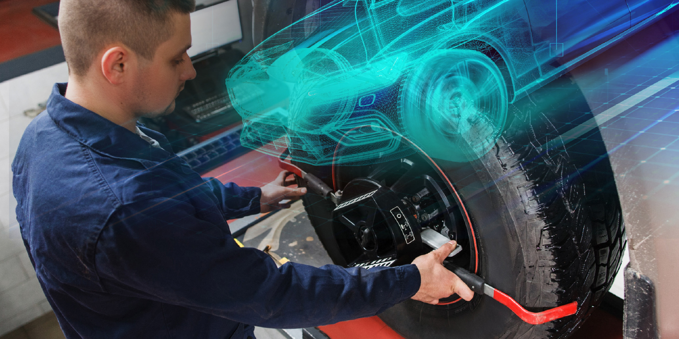
There are many misconceptions floating around about trailer brake controllers. Brake controllers are designed to regulate power from the vehicle to the trailer’s electric braking system. This regulated power ultimately determines the braking force applied at each wheel. The integrated trailer brake controllers (ITBCs) now found on virtually all pickups and SUVs with a tow package must detect the presence of a trailer to activate both lights and brakes, as opposed to the older, simpler aftermarket controllers. Technological advancements are constantly outpacing diagnostic solutions in the automotive industry, causing frustration for shops and customers alike trying to work on these systems. In order to troubleshoot trailer brake controllers, you must first be able to identify and understand the differences between the two types.
The old-style aftermarket trailer brake controllers are “bolt-on” units typically supplied by RV and towing product distributors that depend on sensor inputs for speed and vehicle brake pressure. But, if any of these factors are compromised, the brake controller will not function properly, and sometimes not at all. In 2005, domestic vehicle manufacturers started to integrate trailer brake controllers into their vehicles. The original goal was to provide a seamless trailer braking experience; however, OEMs have started to use the newer ITBC as their own inline, real-time troubleshooting tool.
When working properly, ITBCs provide a superior towing experience by modulating the power and timing to the trailer brakes based upon inputs from vehicle brake pressure and speed sensors. They also have built-in diagnostics via load detection through the trailer electric brake circuit. If the correct load is sensed, power will be sent to the trailer circuit when the brake pedal is pressed. If there’s no load or the wrong load signature is detected, no power is sent or it is removed.
But not all ITBCs are created equal. Understanding how the various systems work makes all the difference for a successful repair and positive customer experience. The following are a few examples of useful information for anyone servicing these vehicles with newer ITBCs.
- Several makes of vehicles automatically limit the output gain if the vehicle is parked, regardless of the user input settings. This is indicated when the technician puts the output all the way up, then checks the voltage at the pin and still gets a low voltage reading. This “false failure” often leads to trucks being mislabeled as faulty due to a false assumption.
- Some vehicles run a continuous discovery pulse to the brake circuit to determine brake connection status. This can be both helpful and dangerous. For instance, while driving, if the vehicle detects the trailer is no longer connected, the ITBC could disconnect power to the brakes. The problem may be the truck, pin connection, faulty brake magnet or an intermittent ground loss. It’s also important to note that not all makes and models use the same discovery protocol.
- Some manufacturers use trailer detection technology on circuits other than the electric brake circuit, such as 12V aux, left/right turn signals, etc. To verify proper operation and troubleshoot problems, you need the right tools to activate these circuits.
With all the differences and lack of suitable tools in the industry, old methods are no longer adequate. A simple resistor such as an incandescent bulb can’t be used to simulate a trailer connection on most systems. Hanging a brake magnet off the truck or even using a trailer only adds additional uncertainty and potential failure points to the troubleshooting process while providing little to no diagnostic value or feedback. In a few years, most light-duty tow vehicles will be able to tell you if any electric component on the trailer goes bad or stops working while driving down the road. With the industry going through this transformation, the right tools need to be introduced before technicians are no longer able to properly troubleshoot these systems.
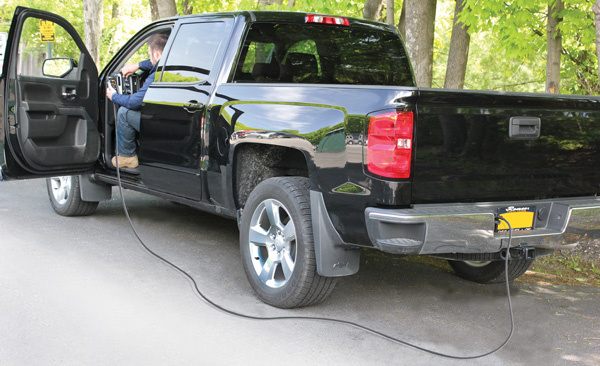
Technicians need to create a load that looks like a trailer, determine if the vehicle’s engine control unit (ECU) is actively working and then view the exact voltage output at the seven-way flat connection at the back of the truck. Then you can determine what the output is when pressing the brake pedal inside the cab. Still, you are left with questions before you can finish troubleshooting. Is the output dependent upon the relative pressure applied to the brake pedal? Does the output application timing change depending upon how fast you press the brake pedal? Does applying the manual brake actuating lever supply full output gain? And most importantly, how are all these factors affected while the vehicle is moving?
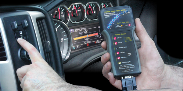
Innovative Products of America has developed a solution to these problems, providing technicians with a one-man troubleshooting tool: the #9107A Electric Brake Force Meter with Dynamic Load Simulation and Circuit Testing. The tool offers techs dynamic load syncing to allow adaption to the various connection protocols required by each OEM without utilizing a brake magnet. Plus, users can compare the actual output of the vehicle with the setting on the brake controller with the truck’s output gain reading in terms of percentage (10%-100%) rather than voltage. The patent-pending technology uses microprocessors to simulate the required trailer load for each vehicle type. Once a connection is established via the 25’ cable, 10 blue LEDs represent real-time output gain and timing. This allows technicians to see exactly what the truck is putting out and relate the information to trailer performance.
Innovative Products of America has been manufacturing tools and equipment in the USA since 1991. IPA’s product categories include trailer testing, electrical maintenance, contact care, diagnostics, abrasives, specialty tools, tire alignment/maintenance, as well as fuel and fluid transfer and filtration. IPA has on-site soldering, CNC, welding, fabrication and mechanical production lines, which are supported by a team of electrical and mechanical engineers. For more information on IPA, visit ipatools.com.