Adapted from Gary Goms’ article in ImportCar.
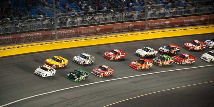
Prior to the Daytona 500 last year, I watched Matt Kenseth blaze his way to victory in the Sprint Unlimited driving a Joe Gibbs Racing Toyota. During the race, one of the commentators referred to the “laser-precision steering” apparent in the winning car. Since driving at 200 mph on pavement is akin to driving 70 mph on black ice, I fully understood what the term “laser-precision steering” means in a racing context. Unfortunately, many of us practicing wheel alignment on production vehicles often fail to understand what the term “laser-precision steering” means when we ignore wear in the ball joints and tie rod ends.
To illustrate my point, a variance in either the toe angle or Ackerman angle caused by worn ball joints and tie rod ends can turn a laser-precision steering system into a non laser-precision driving experience. As we’ll see in the following text, cumulative wear in the ball joints or tie rod ends can actually cause changes in toe angle that not only wear tires, but also create as well a sense of instability for the driver when cornering at highway speeds.
STRESS EFFECTS ON TOE ANGLE
In road-course racing, a steering geometry must accurately navigate multiple types of turns, from sharp hair-pin curves that actually reverse the direction of travel, to what we call “long sweepers,” which are high-speed turns that gradually bend to the right or left and with mild banking to encourage water run-off. Toe angle, of course, is the inward or positive tilt of the forward edges of the front wheels along the centerline of the chassis. The purpose of toe angle is to reduce steering wander and excessive tire wear. In contrast, Ackerman angle is the outward tilt of the inside front wheel when the front wheels are turned away from the vehicle centerline. The purpose of Ackerman is to allow the inner front wheel to follow a shorter turning radius during a sharp turn.
In theory, toe angle should be exactly zero or neutral, which means that the front wheels should align exactly with the centerline of the chassis. In reality, stress forces created at high speeds by the rolling resistance of the tires will force the front wheels into a negative toe angle. Since even a slight toe-out condition causes steering wander by allowing one or the other front wheels to “hunt” grooves and irregularities in the road surface, the main purpose of positive toe angle is to “zero out” the effects of steering linkage flex, and tie rod end and ball joint wear at highway speeds.
THE STEERING AND SUSPENSION RELATIONSHIP
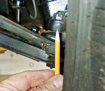
Just recently, I had a classic 1976 Nissan 280Z project car in my shop that illustrates nearly perfect steering linkage geometry. Since the outer tie rod end must clear the tire, the tie rod normally swings through a slightly different radius than does the lower control arm.
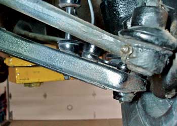
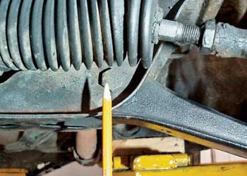
But, in Photo 1, the 280Z’s tie rod end pivots nearly perfectly with the lower ball joint and, in Photo 2, the inner control arm pivots with the inner tie rod end attached to the steering rack. If we hand-press the Z’s chassis up or down by a few inches, we’ll likely see very little toe angle change due to the exact angular relationship between the tie rods and the control arms. See Photo 3.
In race car terminology, we refer to toe change in relation to suspension height as “bump steer.” In Photo 2, our 280Z Nissan project car reduces bump steer by nearly perfectly aligning the tie rod and control arm angles and pivot points. To analyze toe angle and bump steer in real-world terms, remember that excessive positive toe sharpens the outer edges of the tread bars, which creates a saw-tooth effect that can be detected by stroking your hand across the tire tread.
Due to road crown, excess toe angle also shows up as wear on the outer tread bars of the passenger-side tire. In contrast, insufficient toe angle reveals itself as wear on the inner tread bars of the driver-side tire. This phenomenon occurs because excessive toe angle forces the passenger-side tire to “push” the vehicle toward the crown of the road, whereas insufficient toe angle causes the driver-side tire to “pull” the vehicle toward the road crown.
In contrast, uneven tire wear caused by abnormal camber angle will create an uneven wear pattern, but with no sharp edges on either side of the tire tread. With that said, modern tire sidewall designs are much more flexible and much more tolerant of deviations from the ideal toe setting. Nevertheless, a hands-on inspection of tread wear patterns will indicate when toe angle should be changed from the recommended specification.
STRESS EFFECTS ON ACKERMAN
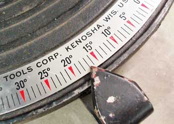
Ackerman angle is adjusted to nearly zero for super speedway racing. But in dirt track racing, Ackerman is typically adjusted to about 1-3° negative toe at a 20° inside turning radius to optimize steering through sharp corners. The rule of thumb for Ackerman on most passenger vehicles is about a 2° split, with 18° outside turning radius at 20° inside turning radius. But due to the unusual stress loading of the front suspension during a turn, ball joint wear can drastically affect Ackerman angle.
Picture this condition as the lower ball joint on the inside of the turn allows the unloaded inner wheel to move in or out. For example, a 1/2° variation in Ackerman angle equals about a 1/4” of toe angle variation. While the 1/2° variation in Ackerman doesn’t sound like much, the 1/4” of toe angle variation does, especially when it comes to providing a laser-precision driving experience. See Photo 4.
CAMBER ROLL
What we call “camber roll” in racing is the quality of increasing positive camber angle on the inner front tire, while decreasing positive camber angle on the outer tire to keep the tire tread in full contact with the road surface during high-speed turns. The amount of camber roll depends very much on the type of tire being used and the severity of the anticipated “G-forces.” In racing, the effects of camber adjustments are checked by measuring the side-to-side temperatures of the tire surface and side-to-side tread wear. In general practice, side-to-side tread wear is the best indicator of correct camber roll under stress.
RACING ALIGNMENTS
Setting up steering geometries for different types of race tracks requires a great deal of record keeping. Professional teams use a computerized program to predict toe, Ackerman and camber roll angles at specific suspension heights. To emphasize how important a few thousandths of an inch wear in the tie rod ends and ball joints might be, many speedway racers attach a flat wheel plate to the wheel hub, which allows them to use dial indicators to measure in one thousandths of an inch the exact amount of toe, Ackerman and camber roll angles present at differing suspension heights and degrees of turning radius.
So the next time you inspect your customer’s high-mileage vehicle, remember that a few thousandths of an inch wear in the tie rod ends and ball joints can defeat even the best-designed “laser-precision” steering system at higher driving speeds.