Ford Tech Tip: Rear Driveshaft Slip Or Bump

Ford Tech Tip: Rear Driveshaft Slip Or Bump

Some 2009-2012 F-150 vehicles equipped with a two-piece driveshaft only and built on or before 7/30/2012 may exhibit a rear driveshaft slip/bump concern on light to moderate acceleration from a stop or when coming to a stop with light braking.

Models:

2009-2012 F-150

Some 2009-2012 F-150 vehicles equipped with a two-piece driveshaft only and built on or before 7/30/2012 may exhibit a rear driveshaft slip/bump concern on light to moderate acceleration from a stop or when coming to a stop with light braking.

Service Procedure

It is not necessary to remove the entire driveshaft from the vehicle for this repair.

1. With the truck in neutral, position it on a lift.
2. Index-mark the driveshaft flange and pinion flange to maintain alignment during installation.
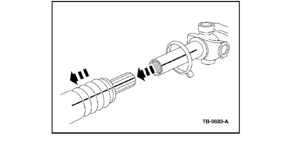
3. Mark a straight line down the slip yoke and driveshaft in line with front slip yoke boot clamp head, to help align for reassembly (Figure 1).
4. Remove the front boot clamp only from the center slip yoke and discard.
5. Remove the four driveshaft flange bolts.
6. Using a suitable tool, disconnect the driveshaft flange from the flange pilot.
7. Remove the rear portion of the driveshaft only – leave the slip yoke boot on the rear shaft.
8. Using a dry, clean, lint-free towel, thoroughly clean old grease from the splines on the slip yoke only.
9. If the vehicle is a 4×4, perform the following procedure. If not, proceed to Step 10.
a. Loosen the center bearing bolts and slide the center bearing fully rearward in the slotted mounting holes
b. Torque the center bearing bolts to 48 Nm (35 ft/lbs).
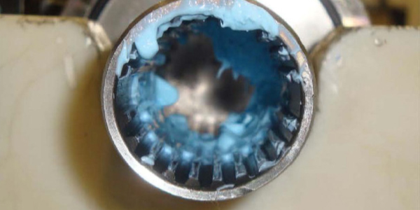
10. Apply an even coat of new grease from the kit to the internal splines of the slip yoke only (Figure 2).

Figure 2

11. Position the new slip yoke boot clamp from the kit over the boot on the spline portion of the driveshaft. Leave clamp loose at this time.
12. Install the rear portion of the driveshaft onto the slip yoke using the alignment marks from Step 3.
13. Apply new threadlock and sealer to the original driveshaft flange bolts.
14. Install the four driveshaft flange bolts using the marks from Step 2 as reference. Torque to 103 Nm (76 ft/lbs).
15. Position the front slip yoke clamp head in-line with the alignment marks from Step 3 and crimp the slip yoke boot clamp.

You May Also Like

ADAS False Activation Evolution

Since 2006, advanced driver assistance systems (ADAS) have evolved from active cruise control to autonomous driving controls.

The average age of a driver in the US is 47 years old. If a driver started at 16, they have seen more than three decades of automotive technology changes. In 2008, ABS became a standard feature on most vehicles. By 2012, stability control, or rollover mitigation, had become standard for vehicles. Since 2006, advanced driver assistance systems (ADAS) have evolved from active cruise control to autonomous driving controls.

Crankshaft Counterweights And Balancing

Imbalance in the engine exhibits vibration and damage. Balancing becomes critical to any engine build.

Diagnosing Misfires

What if there are no codes and a misfire is intermittent? This is where it gets complicated. 

The Importance Of ADAS Calibrations

Following best practices and using appropriate equipment ensure customer satisfaction and safety.

Fuel Pressure Diagnostic Service

Use a scan tool that can look at special direct fuel injection parameters and perform bidirectional tests.

Other Posts

Why Do Vehicles Go Out Of Alignment?

If camber, caster or toe are out of specifications, there is usually a reason why.

Battery Charging and Diagnostics

Here are six tips to use when diagnosing a vehicle with a dead battery. 

Diagnostic Strategies For Stop/Start Systems

This function of the power management system uses several modules to decide when the engine needs to stop and start.

CVT Transmission Service

Like any automatic transmission, the condition and level of fluid in a CVT unit will determine the performance.