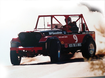
 Judging from weekend traffic, desert off-road and mountain trail driving is becoming a major past-time for many import vehicle enthusiasts.
Most of the off-road vehicles I see in Colorado are the late ’80s and early ’90s Toyota and Nissan pickups and SUVs that feature mechanical simplicity along with the structural ruggedness needed to navigate miles from any service facility.
But there are many issues that a shop must deal with if it services vehicles modified for off-road use.
I’ll try to highlight some of the more common problems and their solutions.
As we’ll see, there’s a lot more to building a rugged off-road vehicle than just raising the suspension height and installing big tires and wheels.
Chassis Check
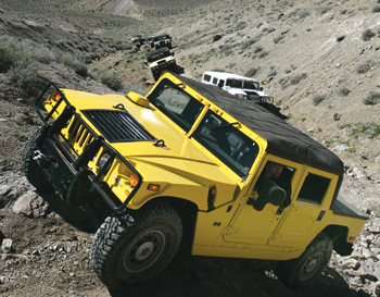
Not all chassis can be modified for off-road use.
Although this Honda CR-V chassis sports all-wheel drive, it would be a prohibitively expensive project to change the suspension and drivetrain geometry on this vehicle to achieve an increase in suspension height. See Photo 1.
Vehicles with automatic suspension leveling and other electronic chassis devices are also difficult to re-engineer.
In addition, it’s important to distinguish between AWD and 4WD vehicles. AWD vehicles don’t include a transfer case with an optional low-gear range for off-road service.
On the other hand, most 4WD vehicles have a low-gear range that allows the driver to creep up and down steep inclines and ease the vehicle over protruding rocks.
Do The Math: Gear Ratios
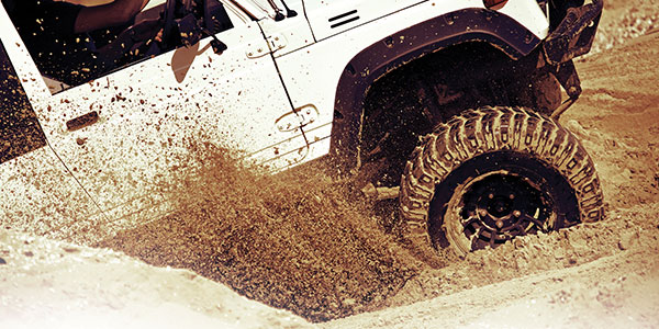
Installing larger-diameter tires and wheels is the quickest way to gain a few extra inches of ground clearance.
But larger diameter wheels have a longer rolling circumference, which provides the same effect as reducing the numerical axle gear ratio.
Because a radial tire changes radius as it presses against the road surface, one can measure rolling circumference most accurately by making a chalk mark on the tire sidewall and measuring the distance required for the tire to complete one full revolution.
Mathematically speaking, a 32-in. diameter tire would equal a 100.53-in. circumference (pi x diameter = circumference or, 3.14159 x 32 = 100.53 in.).
A 28-in. diameter tire would equal 87.96 in. in circumference.
To understand the difference in requirements for the axle gear ratio, dividing 100.48 in. by 87.96 in. indicates that the rolling circumference of the tire is increased by about 114%.
If the vehicle has a 3.73:1 axle ratio, the numerical axle ratio must also be increased by 114% (or 1.14) from 3.73:1 to approximately 4.25:1, to compensate for the increased rolling circumference.
If tire diameter is changed without changing axle gear ratio or the pinion factor, the vehicle speed sensor (VSS) input will be incorrect, which will affect speedometer accuracy, transmission shift quality and possibly even engine performance.
Although using a scan tool on many applications can reset the pinion factor, the vehicle will lack torque in the lower-speed ranges and will generally prove unsuitable for off-road use if the axle gear ratios aren’t changed.
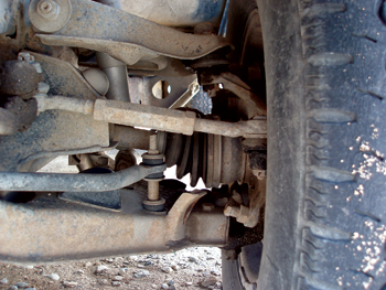
In addition, larger tires must have adequate clearance in the fender wells and against suspension components at full suspension compression and full suspension decompression or “droop.” See Photo 2.
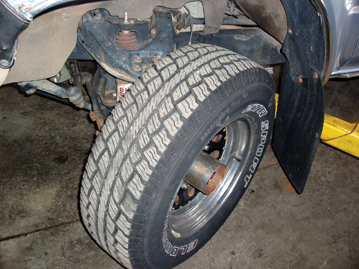
To steer correctly, most vehicles must also allow at least 40 degrees lock-to-lock of steering radius. Of course, some fender-well clearance can be gained by increasing wheel rim offset.
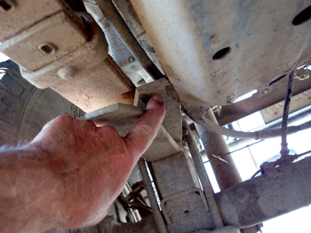
The downside of increased offset is that it moves the tire outboard of its engineered pivot point. See Photo 3.
This means that, instead of pivoting at the approximate center of the tread, the tire now begins to swing through a radius as it is moved outboard. Increased wheel offset increases steering effort and increases loading on the wheel bearings, axle and suspension components. Power steering is generally a “must-have” on vehicles with offset wheel rims.
In addition, larger diameter tires will decrease the stopping ability of the brakes. The only remedy is to install custom brakes with larger-diameter brake assemblies or more swept area. Larger tires with more wheel offset is a trade-off and the advantages must be weighed against the disadvantages.
Applying Geometry: Steering and Suspension Issues
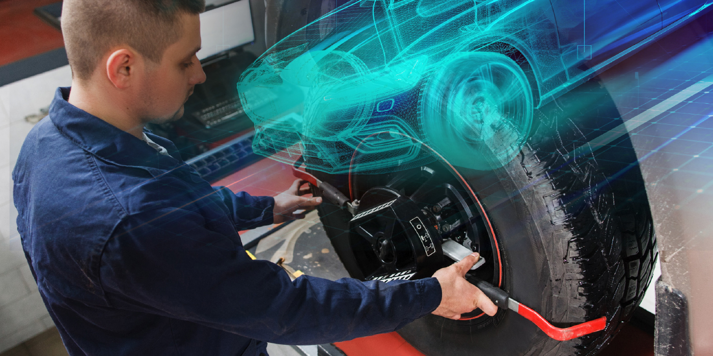
The simplest method of determining how an increase in suspension height will affect wheel alignment and steering geometry is to place the vehicle on a wheel alignment machine and measure the caster, camber and toe angles as the suspension height is being increased.
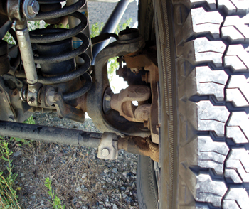
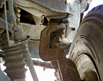
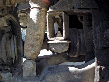
At normal suspension heights, the tie rod is angled slightly downward. See Photo 4.
If a normal weight load is added to the vehicle, the tie rod moves to a more level position. In conjunction with the control arms, the steering linkage is normally designed to maintain toe angle as the springs are compressed.
When the vehicle suspension height is raised, the tie rod angles downward, which causes the toe angle to change from positive to negative as the suspension is compressed.
The same problem affects 4WD vehicles with a solid axle and a drag link connecting the tie rods with the steering gear.
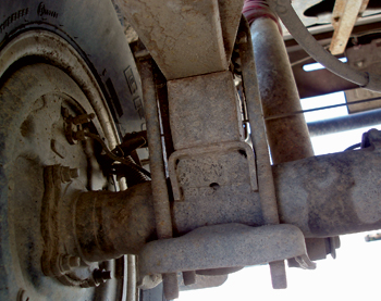
Because the drag link operates through a sharper angle, the wheels tend to steer to one side right when the suspension is compressed. This phenomenon is called “bump steer,” which can cause the vehicle to wander on paved highways. See Photo 5.
In most cases, OE suspensions can be raised only an inch or two without encountering serious steering geometry problems.
If greater height increases are desired, several aftermarket companies may provide modified spindle assemblies designed to increase suspension height without seriously affecting suspension and steering geometry. See Photo 6.
Don’t forget to look at increasing the stiffness of the springs and the diameter of the anti-sway bar or “roll bar” assemblies to help counteract the vehicle’s increased center of gravity on steep slopes. See Photo 7.
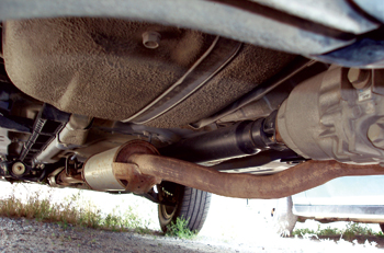
Driveshaft Geometry
Driveshaft geometry is an often-neglected issue on many off-road conversions. If the vehicle has an independent front suspension, the front driveshaft isn’t affected by an increase in suspension height.
If the vehicle has a solid or “live” front axle, the shorter front driveshaft will be most affected because the operating angles on the universal joints will drastically increase. See Photo 8.
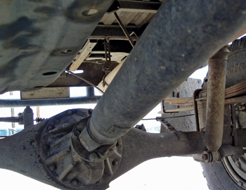
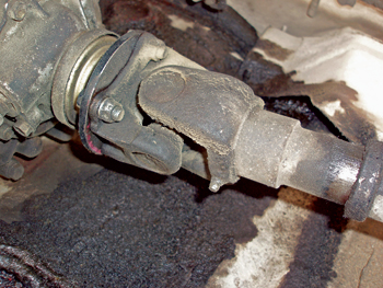
The slip joints are fully extended and the universal joint yokes are most likely to contact each other. The slip joint travel should, for maximum safety and durability, allow at least 2/3 contact between the yoke and driveshaft slip joints.
The slip joint should have at least a 1/2-in. of free travel to prevent mechanical interference at full suspension compression. In some cases, a custom driveshaft must be made to restore slip joint integrity. See Photo 9.
When installing a rear axle assembly, remember that the pinion angle changes as the axle rolls upward with the application of torque. While many stock 4WD vehicles incorporate zero pinion angle, tipping the axle slightly downward would relieve stress on the universal joint.
A tapered caster shim inserted between the spring and axle would equalize the pinion gear angle with the transfer case shaft angle.
Absorbing Shock
Shock absorbers should be selected and installed after the vehicle has been modified. In general, most off-road enthusiasts prefer a heavy-duty shock absorber with more oil capacity to handle increased heat and more rebound control to handle rough terrain.
To prevent breaking the shock absorber, the shock absorber must have enough travel to accommodate the increased suspension height. See Photo 10. Travel should be checked at full compression and full droop.
If the shock absorber is bottoming out at either extreme, a shock absorber with more travel must be installed or the shock absorber mounts must be modified to comply with the increase in suspension height.