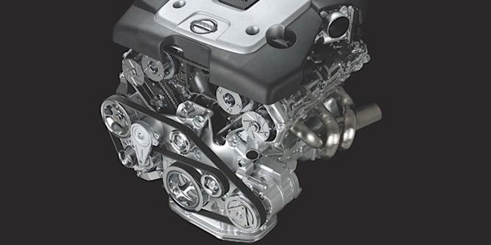
 At the top of the list of the most difficult water pumps to replace are those found in the Nissan VQ-Series V6 engines. The pump is turned by the timing chain and is nestled in the engine block. This can make for a very difficult job no matter if the engine is mounted transversely or longitudinally. The VQ35 series of engines can be found in 2001-current Nissans and Infinitis. Book time on this job can range from 2.0-3.0 hours depending on the model and layout. Unfortunately, there are no shortcuts.
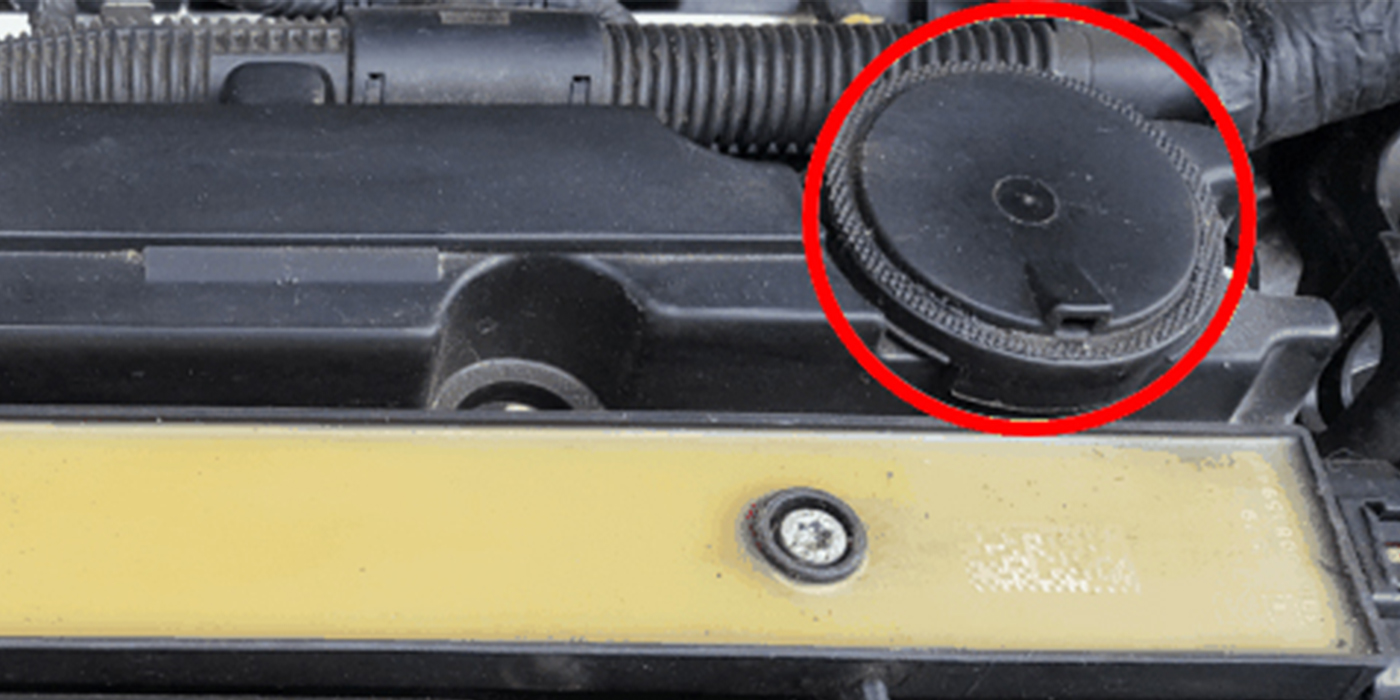
The first sign of water pump bearing failure will be a coolant leak coming from a hole on the block by the air conditioning bracket. This hole leads to the weep hole on the pump. The hole is between two seals that separate the oil on one side and the coolant on the other. If the outer O-ring fails, it will leak coolant into the front cover area that is connected to the oil sump. This could mimic a head gasket leak.
When replacing the pump, pay close attention to the O-rings. These need to be lubricated with either oil or coolant. The rings need to be able to seal and move small amounts as the block heats and cools. Do not use silicone or other sealants. These can block the weep hole in the block.
Before starting the job, set the engine to top-dead-center. This can prevent the cams and engine from wanting to flop over when you release the slack on the chain. If you exceed 20º with the tensioner slacked, it could cause the chain to jump.
Removal
1. Drain the coolant.
2. Remove the right-hand side engine cover.
3. Remove the coolant reservoir.
4. Remove any components or portions of the wiring harness that may block access.
5. On transverse-mounted engines, remove the right-hand tire and splash shield.
6. Remove the drive belts.
7. Remove the idler pulley, then the power steering and generator adjusting bars.
8. Support the engine and remove the front engine mount and bracket.
9. Remove the water drain plug on the water pump side of the cylinder block.
10. Remove the chain tensioner cover and water pump cover.
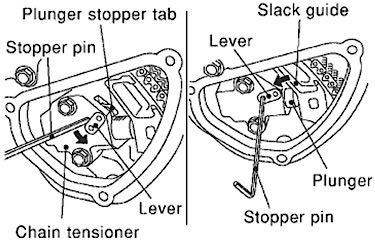
11. Remove the chain tensioner assembly.
a. Pull the lever down and release the plunger stopper tab.
b. Insert a pin into the tensioner body hole to hold the lever and keep the stopper tab released (Figure 1).
c. Insert the plunger into the tensioner body by pressing the timing chain slack guide.
d. Keep the slack guide pressed and hold the plunger in by pushing the stopper pin deeper through the lever and into the tensioner body hole.
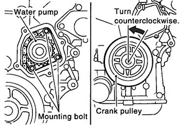
e. Make a gap between the water pump gear and timing chain by turning the crankshaft pulley approximately 20° clockwise (Figure 2).
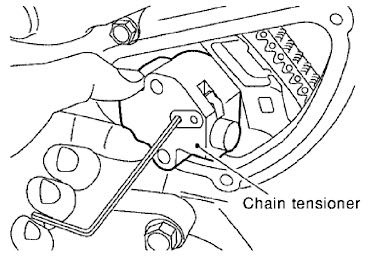
12. Remove the chain tensioner. Be careful not to drop bolts inside the chain case (Figure 3).
13. Remove the three water pump bolts. Make a maximum gap between the water pump gear and timing chain by turning the crankshaft pulley counterclockwise until the timing chain loosens on the water pump sprocket.
14. Screw M8 bolts (pitch: 1.97 in.) into the water pump’s upper and lower mounting bolt holes until they reach the timing chain case. Then, alternately tighten each bolt for a half turn and pull out the water pump. Pull straight out while preventing the vane from contacting the pump housing or chain.
Installation
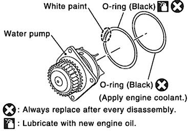
1. Install new O-rings onto the water pump.
2. Apply engine oil and coolant to the O-rings (Figure 4). Aftermarket pumps may have different colored O-rings and lubrication procedures.
3. Install the new water pump. Make sure the O-rings are in their grooves when installing the pump. Check that the timing chain and water pump sprocket are engaged. Insert the water pump by tightening the bolts alternately and evenly. Water pump bolts: 8.5-10.7 Nm (75-95 in.-lbs.)
4. Remove dust and foreign material completely from the backside of the chain tensioner and from the installation area of the rear timing chain case.
5. Turn the crankshaft pulley approximately 20° clockwise so that the timing chain on the timing chain tensioner side is loose.
6. Install the timing chain tensioner. Timing chain tensioner bolts: 7.0-9.3 Nm (62-82 in.-lbs.)
7. Remove the stopper pin.
8. Install the chain tensioner and water pump cover. Remove the old sealant and apply new.
9. Refill the engine with coolant.
10. Start the engine. You may hear the timing chain rattle at first. Rev the engine to 3,000 rpm to purge the air from the chain tensioner.
Article courtesy Underhood Service.