Nivomat is a contraction of two French words, “niveau” and “automatique.” In English, it translates as level automatic or automatic level.
The system makes use of the mechanical energy which is generated during the first feet of driving from the relative movement between the axle and vehicle body.
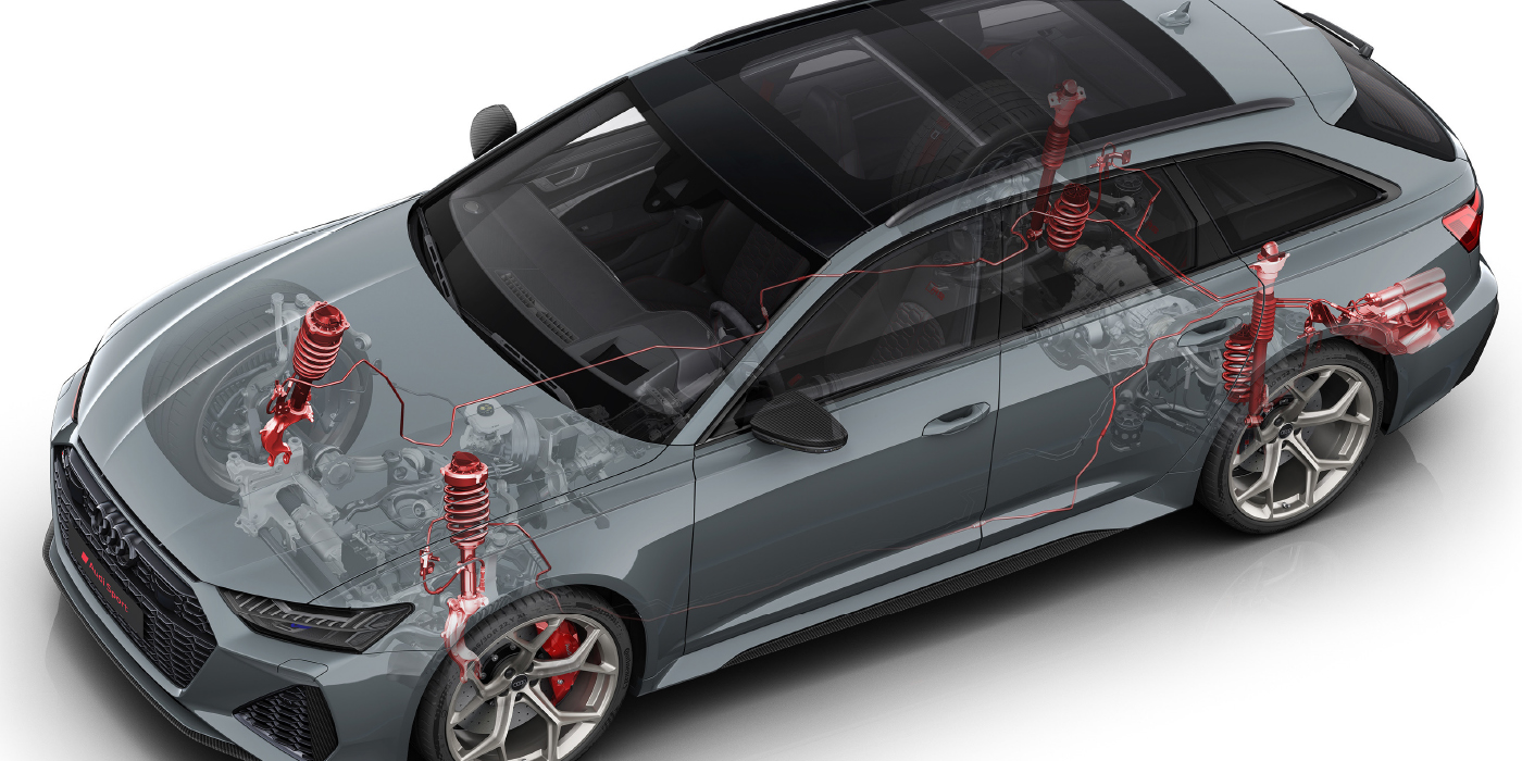
The Nivomat system does more than just level the vehicle under load. As the load increases, the pressure inside the shock increases as oil is displaced from the reservoir to the inside of the unit, compressing the gas volume. This creates a progressive increase in spring rate and damping with little or no change to ride frequency.
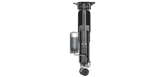
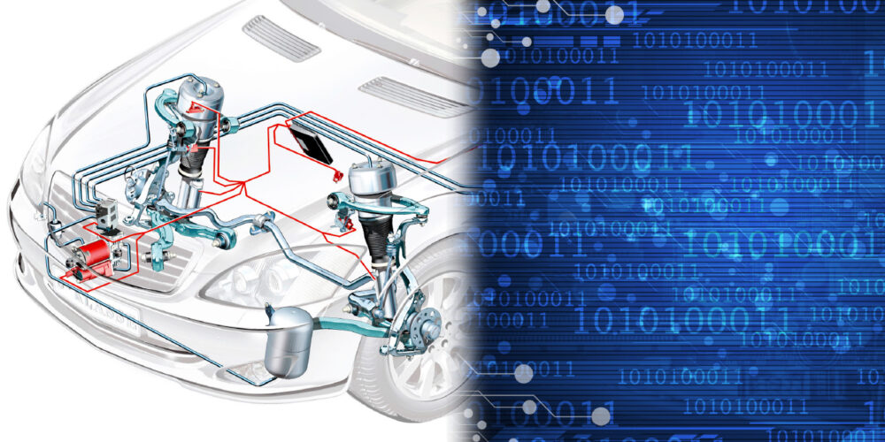
What gives the shock its leveling capability is a pump mechanism and oil reservoir that can increase the accumulator pressure, which increases the shock’s lifting capability. It is used in combination with springs matched to the load capacity of the shock to reduce suspension travel while utilizing more of the piston and shaft travel of the shock.
The accumulator can be a diaphragm or piston. The normal pressure contained in the accumulator ranges from 20 bar (290 psi) to 50 bar (725 psi). The pump can increase the accumulator pressure from 90 bar (1,305 psi) to 130 bar (1,885 psi). Under driving conditions, pressure can reach 350 bar (4,424 psi).
The Nivomat shaft and piston provide the same damping as a normal monotube shock. The difference is that the shaft is hollow and contains the pump mechanism. The pump is operated by the displacement of oil caused by the movement of the shaft in and out of the shock. When the piston shaft moves out of the shock, oil is drawn from the low-pressure oil reservoir through the hollow pump rod and inlet valve into the pump chamber.
Since Nivomat is mechanical, the vehicle needs to be moving before the pump starts to work and it takes about a mile to a mile-and-a-half of travel before the vehicle reaches its optimal level point.
Article courtesy Brake & Front End.