The topic of noise, vibration and harshness (NVH) diagnostics came home to me 20 years ago when I began dabbling in collector car repairs. Customers soon began complaining about wind noise and chassis vibrations in ‘60s-era cars. Back then, these complaints weren’t repairable because good NVH abatement technology had yet to be developed. Today, that is not the case.
Thanks to their efforts, vehicles now have these NVH advancements:
- Engine balance shafts continue to cancel reciprocal engine vibrations. Electronically controlled hydraulic engine mounts dampen engine-to-chassis vibrations.
- Advanced-design radial tires and machined alloy wheels now eliminate most wheel and tire runout problems.
- Flush-mounted windows and precision-fitted doors and body panels have vastly reduced wind noise complaints.
- Electronically adjustable ride control has reduced many ride-related harshness complaints.
- Better sound-dampening insulation in the body has reduced road and powertrain noise levels to the point that many daily drivers now operate as quietly as the finest luxury vehicles.
On the flip side, each NVH refinement has served only to increase the driver’s sensitivity to noise, vibration and harshness. In the following text, I’ll introduce you to some of the basic terminology and testing techniques used in modern NVH diagnostics.
OLD-SCHOOL NVH ISSUES
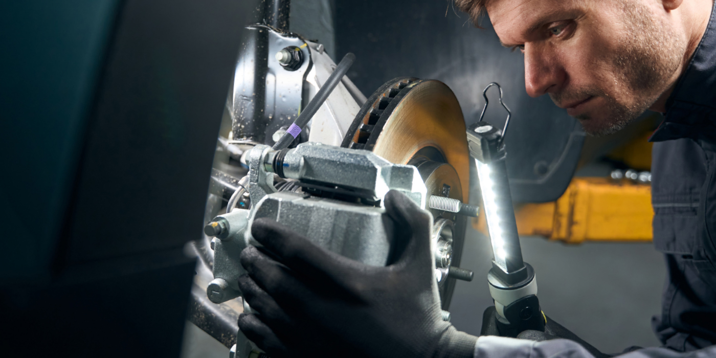
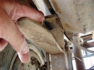
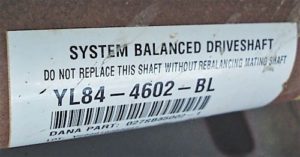
During my dealership days, most new-vehicle NVH complaints were caused by obvious sources like inaccurately machined, poorly assembled or broken parts (See Photo 1). Noise and vibrations were a slightly different story since seat-of-the-pants diagnostics can’t accurately quantify their frequency and amplitude. In contrast, most harshness complaints involve ride control issues, which are generally subjective complaints that involve a newly installed set of heavy-duty shock absorbers or over-inflated tires.
NVH MATH
While many old-school NVH issues continue to be diagnosed by a sharp ear or by an experienced seat-of-the-pants feel, most modern NVH diagnostics require quantifiable data. In contrast to old-school complaints, many modern noise/vibration complaints are caused by harmonic or resonant noises emanating from body or interior panel parts that vibrate or resonate in response to variations in road surface, engine speed, vehicle speed and wheel speed conditions.
Diagnosing these complex noise and vibration issues typically requires a PC-based labscope equipped with NVH diagnostic software and hardware that displays, calculates and compares data. But to analyze NVH data, we need a basic appreciation of the math and terminology they use.
To illustrate, noise and vibration are generally quantified in frequency and amplitude. Frequency can be expressed as revolutions per minute (rpm) or cycles per minute (cpm), or as hertz, which is revolutions or cycles per second. Amplitude, on the other hand, indicates the relative severity of the noise or vibration. By using software applications, we can compare the amplitudes of different noises and vibrations.
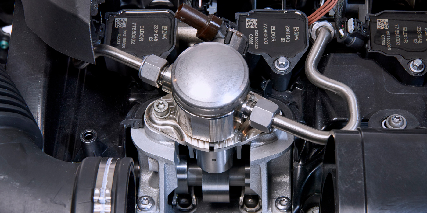
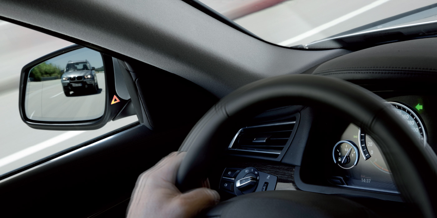
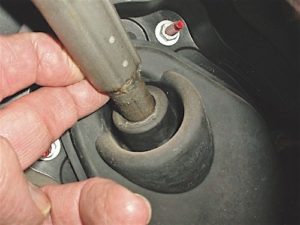
Wheel-speed- and engine-speed-related noises and vibrations are common NVH complaints. To diagnose wheel-speed vibrations, frequency and vehicle speed, tire size and axle ratio must first be determined. To diagnose engine vibrations, their frequency, engine rpm, and, in some cases, the engine’s accessory pulley drive, diameters must be determined. Many of these vibrations occur at specific wheel or engine speeds (See Photo 2).
For example, to quantify the exact diameter and rotational frequency of a tire, a basic math formula might include the tire’s aspect ratio, tire size, wheel rim diameter and a mathematical constant to simplify calculations. To quantify the tire’s rotational frequency in hertz, the tire diameter can be multiplied by miles per hour and divided by a mathematical constant. Multiplying wheel speed frequency in hertz by the drive axle gear ratio equals a driveshaft’s rotational frequency. The math can vary with the tooling, so follow manufacturer’s specific instructions.
“Orders of frequency” are also part of NVH terminology
- Engine crankshaft speed vibrations (e.g., harmonic balancer or an out-of-balance torque converter) are first-order vibrations.
- Accessory drive vibrations are considered second-order vibrations.
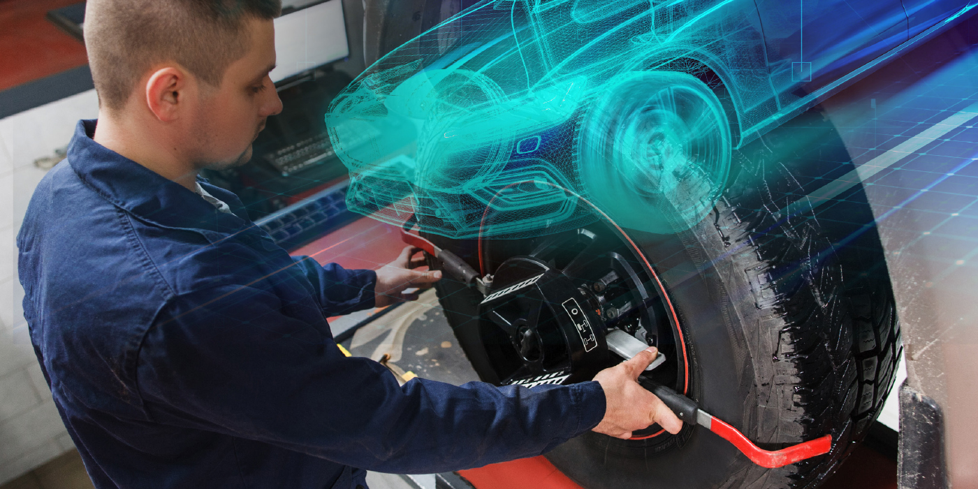
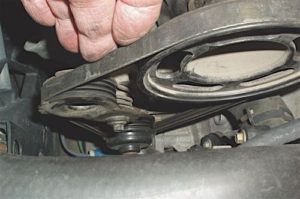
- If the propeller shaft is operating at excessive or unequal angles, it’s considered a second-order vibration (See Photo 3).
- A worn constant-velocity joint might be considered a third-order vibration because the axle shaft is operating off-center and because the worn CV joint could be causing a torsional vibration during turns.
The term “transfer path” indicates the path along which a noise or vibration is transferred from its source to a resonating component. Some examples include: A steering wheel resonating with a vibration that begins at the wheels and travels through the steering linkage and steering shaft to the steering wheel; a driver’s seat resonating with vibrations transferred from the wheels through the chassis; a buzzing glove box lid resonating with engine vibrations travelling through the engine mounts and into the body; and springs functioning as transfer paths for noises emanating from pitted wheel bearings or worn universal joints.
MODERN NVH TOOLING
For a long time, import manufacturers have been devising many different types of tooling for detecting the frequency and amplitude of noises and vibrations. Among technicians, chassis microphones continue to be a popular tool that quickly pinpoints the sources of the chirps and squeaks that represent most NVH complaints.
Software applications for PC-based labscopes continue to be the most versatile and accurate tools for diagnosing complex NVH complaints. PC-based scopes provide larger screens and more data channels than some of the older dedicated NVH analyzers.
The labscope allows the technician to display and compare several noises or vibrations in terms of frequency and amplitude, which is handy for separating complex issues like resonant passenger compartment noises caused by seized universal joints or pitted wheel bearings.
THE NVH MARKET
NVH diagnostic activities are often considered a “necessary evil” because they’re not big profit centers. On the other hand, if an import shop develops a familiarity with the NVH problems associated with a single manufacturer’s platforms, the shop can diagnose NVH complaints in a more cost-effective manner.
Remember, some of the best aftermarket tooling is rebranded and supplied to dealers as OEM-required equipment. So, if you are specializing in a specific nameplate, it will pay to look at OEM as well as aftermarket options before choosing NVH software and support equipment.
Not All Customers Hear Alike
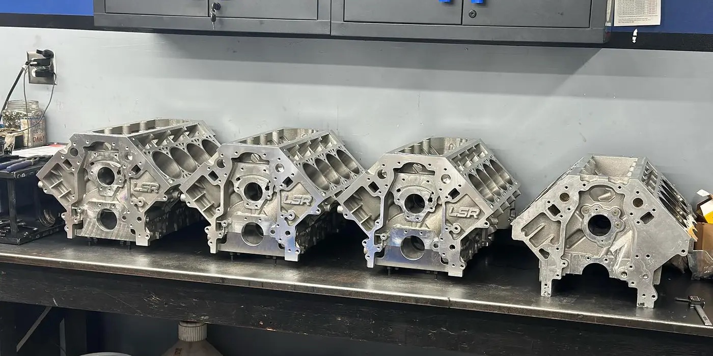
I don’t think it’s a big secret that not all customers hear alike. On a personal level, I can hear a pin drop, but I can’t hear some tonal variations in the human voice. Similarly, a vehicle owner might hear the squeak under the dash while blissfully ignoring the knocking noise under the hood. For that reason, test driving is a vital first step in separating the customer’s subjective NVH concern from your objective data (see Photo 4).
Specific driving conditions related to the concern are very important. A clicking brake pad might be discernible only when driving up to the drive-in window at the local bank. The mild “chucking” noise produced by a set of worn stabilizer link bushings might occur only when driving over washboard roads at 25 mph. Aggressive tire treads might make loud whining noises on a cement road surface, but not on an asphalt surface.
The following mental checklists are critical for diagnosing NVH concerns.
1. Make sure that all the tires are properly inflated, that all have the same size and tread depth, and that all lug nuts are torqued to specification.
2. Check for bike racks and other external aftermarket accessories that might produce harmonic noises at various speeds.
3. Check for “trunk junk,” (i.e., loose spare tires, jacks, metal toolboxes and loose items) that tend to collect in a car’s trunk over time.
4. Check the glove box for loose change and other noise-making objects.
5. Look under the hood to make sure that the battery is secured, that all drive belts are correctly tensioned and that plastic engine covers are secured.
6. Once the vehicle is on the lift, check all rubber engine and transmission mounts, ride control mounts, suspension bushings and exhaust hangers for deterioration.
The list of noise-making components can be endless, but inspect all the “stupid stuff” first. For less obvious NVH concerns, search the manufacturer’s TSBs to correctly identify specific NVH concerns and recommend corrective services. Above all, remember to charge for time and testing, both of which are vital to the NVH bottom line.
Article courtesy Brake & Front End.