One of the most basic circuits found on every gasoline powered vehicle is the ignition coil. This transformer takes low-voltage, high-amperage current and changes it into high-voltage current. It has two windings that are not physically connected. What does connect them is magnetism. The primary creates an electromagnetic field when system voltage is applied. When the power is turned off, the magnetic field collapses. The energy from the primary is transformed by the secondary windings into high-voltage power that can jump the gap between the electrodes of the spark plug; this is called inductance.
It is a very simple and robust circuit. But, why does it give technicians problems when diagnosing ignition-related misfires? The answer is that some technicians use tests that might give inconclusive results or do damage to the coil or drivers inside a module.
Swap Test
There is a diagnostic method called “swaptronics” or “swapnostics” to isolate misfire codes. This technique involves swapping coils to see if the misfire code follows the defective coil. Depending on the vehicle and the type of coil failure, it can work. But, on some engines, it can damage an engine or ignition control module.
Let’s say the ignition coil for cylinder number one has a short to ground of the primary circuit. It happens when the resin inside the coil breaks down due to heat and vibration. Instead of the typical four ohms of resistance, there is now zero resistance. In rare cases, the current in the secondary can make its way into the primary windings.
If the technician is lucky, the driver circuit is in the coil assembly, and only the coil assembly will be damaged. If the coil driver circuit is in the ECM on the main circuit board, the ECM will more than likely be damaged. When you swap the coil to the next cylinder, you just damaged another driver on the circuit board. But, now you have two misfires instead of the one you started with.
Some OEMs have even issued strongly worded TSBs advising against swapping ignition coils. It is also a procedure you will never see on a diagnostic flow chart. The advice from most OEMs is to test the primary side of the coil for damage and check for a driver signal from the ECM. If one coil is damaged or the control signal for the coil is missing, the ECM should be replaced along with all the coils.
How could swaptronics damage be avoided? The answer is proper diagnostics. If the misfire code is cylinder-specific, check for other codes. Often, there will be a code for the coil’s circuit like P0356 for a short in the primary’s circuit. If there are no codes, you can test the coil with a scope or meter.
Open-Air Test
One test to avoid performing is removing a coil or plug wire to see if a spark is present. First of all, this test will only tell you that the ignition system has control and is able send power to the primary side of the coil. If the spark plug does produce a spark, the spark you are witnessing is at 14.6 psi and not the 170 psi or more inside the cylinder during the top of the power stroke. In rare cases, the uncontrolled spark could damage other electrical components like the coil next door. Do not remove the coil’s connector while the engine is running to see if a misfire or rough running condition changes. Some OEMs advise the connector should never be removed if the key is in the on position.
What Tests Should You Use?
Your first tool for diagnosing an ignition issue is your eyes. Spend some time inspecting the coil’s connector, boot and the spark plug. Often, the cause of an ignition system problem will present itself.
One of the best ways to test the condition and output of a coil is by using a capacitive probe to measure the secondary ignition waveform. If you can’t find a “known good” waveform, compare the waveform to another coil on the engine. To test the primary side of the coil, you can use a current probe placed around the positive wire going to the coil. With this test, you can see if the power is being sent to the coil and if the engine management system is controlling the coil by the current ramp.
If you look at a secondary ignition waveform on a scope, you will see a spike representing the coil’s output. I know what you are thinking: if the ignition coil has a fixed ratio of primary and secondary windings, and the system voltage is constant, shouldn’t the spike be the same all the time? In theory, yes. In practice, the spark plug and mixture of air and fuel inside the cylinder can determine how high the spike will go on your scope.
The key with the spike and spark line is to compare it to the other coils on the vehicle. If one spike goes higher than the rest, it signifies two things. The resistance in the combustion chamber could be different than the rest of the cylinders, or the spark plug could be worn. If the spike is significantly lower than the rest of the cylinders, it is a sign that the resistance is lower in the plug or cylinder. Sometimes, a clogged or dead fuel injector can cause a lower spike when the throttle is snapped.
Why Coils Fail
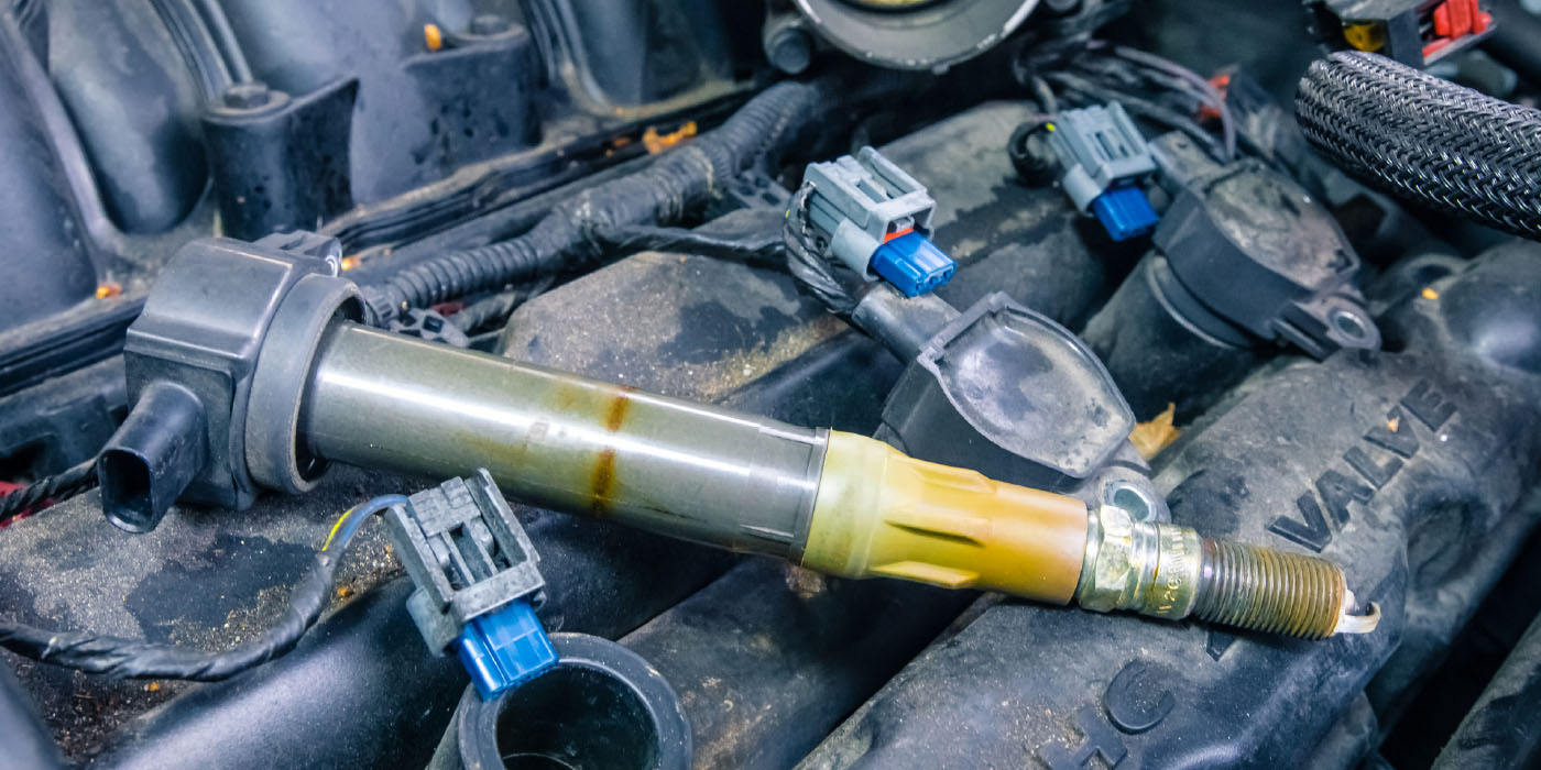
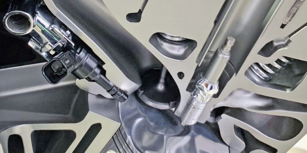
What kills ignition coils is location; being mounted in one of the hottest, most vibration prone and dirtiest parts of the engine. Modern ignition coils are typically located between two camshafts on the valve cover and exposed to dirt and oil. But, even if a coil is mounted in a cool, clean and vibration-free environment, if the gap on the spark plug is not correct or there are issues with high resistance in the cylinder, it won’t take long for a coil to fail.
The windings in the primary and secondary eventually break down and hopefully the primary and secondary turn into an open circuit. The worst-case scenario is the voltage from the secondary finds its way into the primary and eventually the driver for the coil. This is why you do not swap coils to diagnose a misfire code.
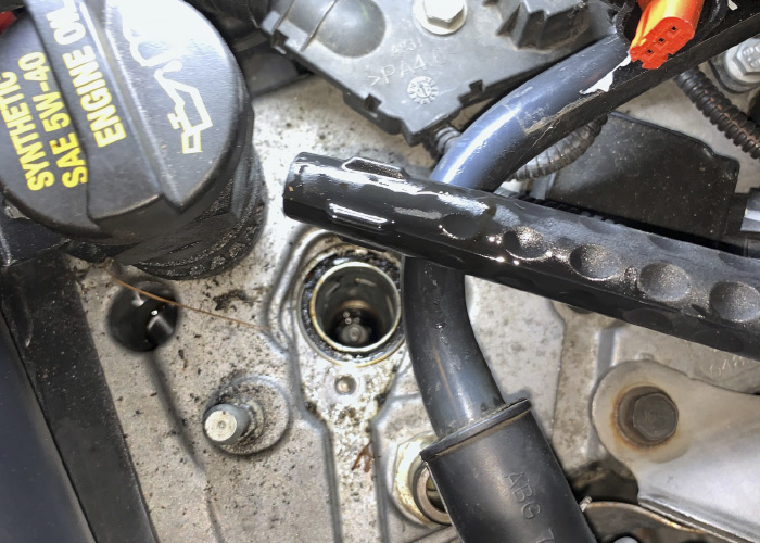
Some problems are due to conditions in the spark plug well. When the power from the secondary is traveling through the boot, ignition wire and spark plug, it creates static electricity that causes oil and dust in the area to stick to the component. You have probably seen this condition on spark plugs where the ceramic insulator is exposed on the side of a head. The spark plug can have a yellow or orange band that is called a corona stain. Some technicians mistake it for exhaust gases leaking between the shell and insulator. If enough material builds up on a boot or plug it can create a path of least resistance for the electricity generated by the secondary.