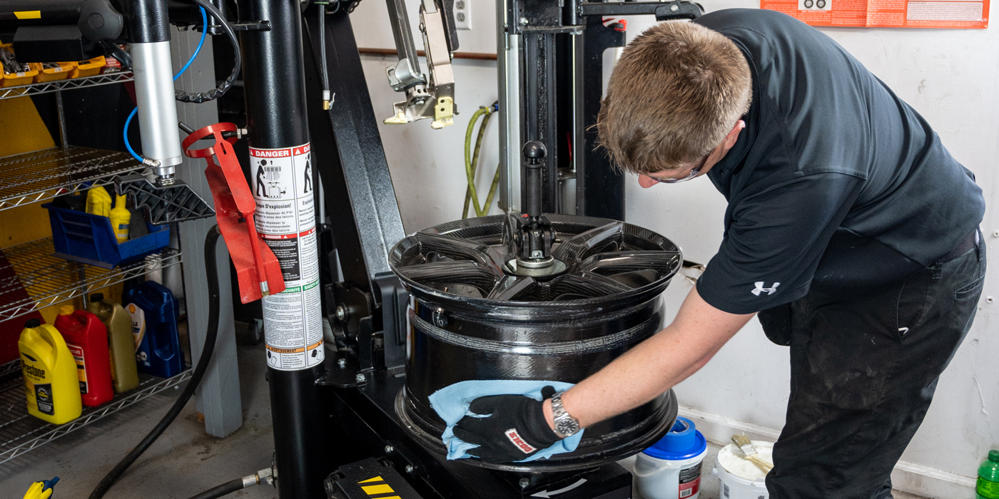
You just finished a car or truck alignment or other repair that might have disconnected power to the vehicle. You pulled the vehicle off the lift and parked it in the lot. The customer pulls away and, within five minutes, they are back complaining an ABS, stability control or ADAS light is illuminated or a warning message is displayed. What happened?
When you scan for codes, you will find codes C1306, C1307 or another proprietary DTC indicating a malfunction with the steering angle sensor. Depending on the vehicle, these codes indicate a malfunction, inability to find the center or end stops, or missing calibration of the steering angle sensor.
Ninety percent of the time when a steering angle sensor code is active, it means the sensor needs to be calibrated. The other 10% of the time, the sensor has failed or there is an issue with the communication network sharing the data from the sensors.
The calibration process typically involves learning the center and end stops of the steering rack. Some systems require a static calibration in a bay with a scan tool attached. Others require a dynamic calibration which might need to be initiated with a scan tool. Other systems will perform the calibration automatically after a drive cycle.
If the calibration process can’t be completed, it will set a code for the steering angle sensor. Some proprietary codes will indicate why it aborted a steering angle sensor reset. If a code is not active, look at the datastream PIDs to see if the data changes when the steering wheel is moved.
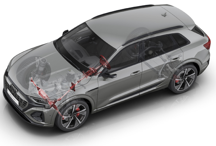
If you are looking for the steering angle sensor data, it could be in several modules. Conventional systems connect the steering angle sensor to the ABS module, which is connected to a high-speed network like CAN. Vehicles with electric power steering typically have the sensors connected to the steering module that communicates with the engine control module to ensure engine speed does not drop when the driver turns the wheel. The steering module is connected to a CAN bus with the ABS and ECM. Another configuration might be to have a “sensor cluster” that communicates on the CAN network on its own.
The steering angle on your scan tool might be in degrees, but on some vehicles it could be a numerical value. Check the service information for the correct values. Most scan tools will have data from two steering angle sensors. Some vehicles will not use zero as the number for centered. Look at the service information. Also, some vehicles might require calibrating the motor position sensor that is located on the rack.
Engineers use two or three steering angle sensors in the column for redundancy and to double-check data. For some vehicles, the angle will have 180 degrees of difference. Other sensors that reveal data and codes are the yaw and lateral acceleration sensors. Dynamic-calibration vehicles will look at data from these sensors to confirm a change in steering angle results in a change in direction for the vehicle. If the sensor is not working or has active codes, a static or dynamic steering angle recalibration will not be possible.
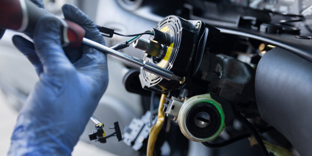
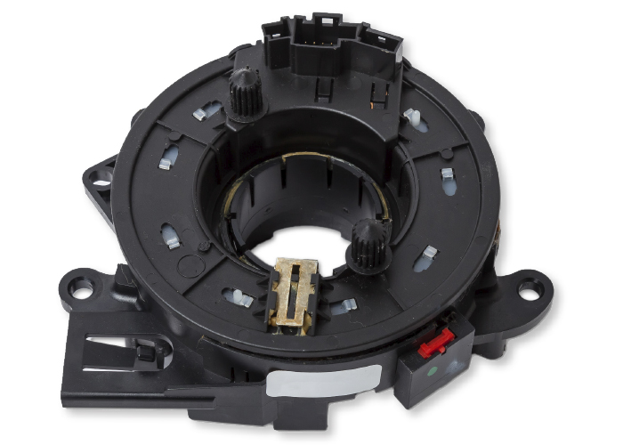
On some vehicles, the steering sensor cluster is part of a module that may include functions for the turn signals, steering wheel, audio controls and wipers. This module is not a box, but part of the column and might have multiple CAN lines coming out of it. Often, the SAS cluster cannot be replaced on its own, instead requiring replacement of the entire unit.
ADAS CONNECTION
The steering angle is used by many ADAS functions, from blind-spot detection to autonomous driving. If the steering angle sensor is not calibrated, it could lead to the false activation of many ADAS systems. The most annoying malfunction is the false activation of the lane departure system. Even the smallest of errors in the SAS can make the vehicle think the driver is trying to steer into an oncoming lane. Some systems may just shake the seat, while other systems might try to steer the vehicle back into the lane.