Many years ago, I watched a co-worker pulling into the parking lot in his classic Chevy convertible. He seemed to be waving at someone or maybe shooing a fly away. I wasn’t really sure, and I didn’t think enough of it to ask, but later in the afternoon I learned what he was doing.
It turns out the accelerator cable had broken. To make it to work, he connected a piece of string to the carburetor linkage, then ran it through one of the hood louvers and over the top of the windshield so he could control the throttle. “Hey, it worked,” was his response to friendly ribbing.
The fact is it did work, and as rudimentary as it may have been, it‘s this type of simple mechanical connection between your foot and your engine (although a little better than string) that has allowed us to make a car go since the days when they were no more than a horseless carriage. Either a mechanical linkage or a cable was utilized to connect the throttle control inside the car to the carburetor or fuel-injection throttle body on the engine.
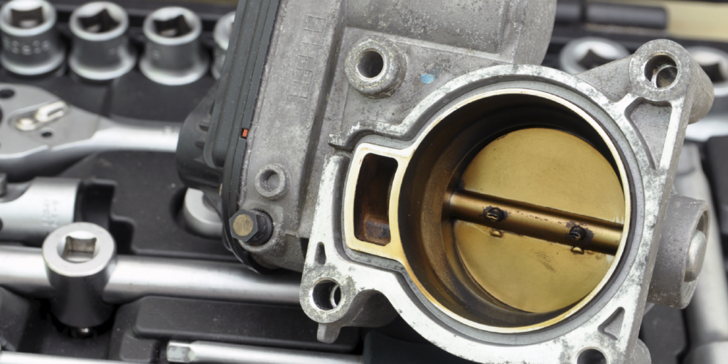
First showing up in the late 1980s, the ETB (electronic throttle body) is now the device that controls airflow into the engine on the majority of the vehicles on the road today. What is an ETB? Like a lot of modern electronics, the name can seem daunting, but they’re pretty simple when you break it down.
The chronology goes like this: Carburetors were simple mechanical devices. All you were doing was controlling air flow into the engine. The carburetor did the rest. Next, along with fuel injection, came the throttle body. The computer, fuel injectors and engine sensors worked together to control the amount of fuel supplied to the engine. All you were doing was controlling the air flow through the throttle body into the engine.
So what’s quicker, more efficient and more dependable than a mechanical connection? Electricity of course – making the ETB the only logical step in powertrain management.
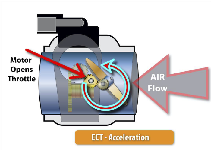
How do they work? An ETB is a throttle body that looks in appearance and function as they always have, with the exception of a small electric motor in place of a mechanical linkage. The electric motor, in response to commands received from either the ECM (engine control module) or PCM (powertrain control module), is what opens and closes the throttle plate inside the throttle body. The only thing connected to an ETB is wires.
Different manufacturers use different systems, but the basis of ETB operation is the same regardless of what your customers are working on. The accelerator pedal in the vehicle contains sensors that transmit information about pedal position to either the ECM, PCM or in some cases, a dedicated ETB module.
The ETB system logic takes into account the information from the accelerator pedal as well as a number of different systems and sensors such as vehicle cruise control, speed sensor and MAF (mass airflow) sensor and then determines how far to open the throttle plate inside the throttle body.
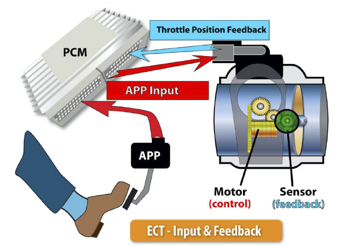
And finally, there are additional sensors within the throttle body that transmit information back to the ECM so that it knows that the requested throttle position has been met.
Most late-model vehicles have an average of 60 to 100 sensors on board. However, due to rapidly advancing technology, the number of sensors is projected to reach up to 200 per car in the next few years.
The internal combustion engine (ICE) is increasingly controlled by “smart sensors” that feed data to multiple on-board computers.
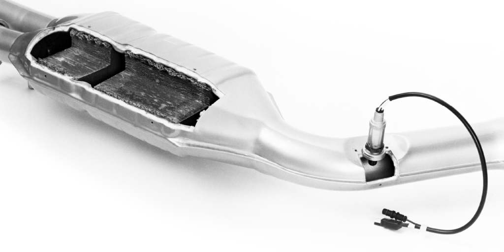
Oxygen sensors are vital to an ICE engine because of their role in controlling the fuel-injection system and emissions. An O2 sensor works in tandem with the ECU and other components to allow the injector to pulse the right amount of fuel into the cylinder during combustion. The primary function is to maintain efficient combustion and not be too lean or too rich. If the sensor detects unburned fuel, it will relay a voltage signal to the ECU, telling it to reduce the amount of pulse width to the injectors (fuel), depending on the demand of the driver’s right foot and other conditions.
Mass airflow (MAF) sensors measure the volume and density of air entering the engine at any given time. The ECU uses this information, along with input from other sensors, to calculate the correct amount of fuel to deliver to the engine. Data from this sensor helps calculate ignition-timing and transmission-shifting strategies.
Similar in function to the MAF sensor, the manifold absolute pressure (MAP) sensor measures manifold pressure and relays the information to the ECU. The information is used to calculate air density and determine the engine’s air-mass flow rate.
Late-model engines with electronic fuel injection, computerized fuel management and ignition have a lot of sensors to keep tabs on everything that is happening under the hood. Most sensors produce a digital voltage signal that corresponds to the function they are monitoring.
All of this sensor data is fed back to the Powertrain Control Module (PCM) so it can make the critical decisions that are necessary to keep the engine running at optimum efficiency. Among all the sensors, these are usually the five most critical:
• Throttle Position (TPS) sensor — This sensor is mounted on the throttle body shaft to monitor the relative opening of the throttle. The PCM uses this information with inputs from the MAP and/or MAF sensor to estimate engine load for fuel enrichment and timing adjustments. A worn TPS sensor may cause a flat spot or hesitation when accelerating. On vehicles with electronic throttle control, there are usually two TPS sensors as well as a pair of position sensors on the accelerator pedal. The position sensors on the accelerator pedal tell the PCM how much throttle opening to give the engine when the driver steps down on the gas. The TPS sensors on the throttle tell the PCM how far the throttle is opening or closing as commanded by the PCM. Problems here may prevent the throttle from opening or even cause unintended acceleration.
Crank-position sensors (CKP) are one of the primary electronic devices used to monitor the position and speed of the crankshaft for purposes of feeding the information to the PCM to control the fuel injection and ignition timing and other engine parameters.
A throttle-position sensor (TPS) is located on the butterfly spindle/shaft so it can directly monitor the position of the throttle. Some sensors also are used as an extra closed throttle-position sensor (CTPS) to indicate that the throttle is completely closed. These sensors also can be part of electronic throttle control (ETC) or “drive-by-wire” systems.
The benefits of an electronic throttle control system include overall reliability, since there are far fewer mechanical components that can wear out or require adjustment over time. Vehicles accelerate smoother with an ETB and they provide the precision required for the advanced systems in modern vehicles such as traction control, launch control and adaptive cruise control.
Is there a negative side to an ETB? Not from where I sit. Most new technology, especially in the automotive world, gets a bad rap until people become comfortable with it. Sure, it might be easier to diagnose a broken throttle cable than an electronic or wiring problem, but this is today’s world and today’s technology. It’s better than it ever was, and those who learn it are ultimately those who love it.