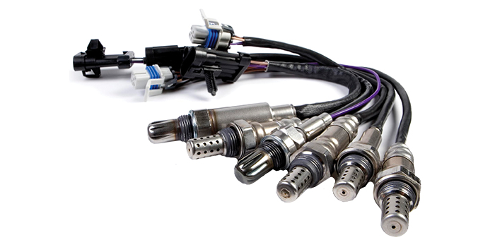
Oxygen sensors are used to monitor the engine’s air/fuel mixture so the powertrain control module (PCM) can make adjustments that optimize fuel economy, emissions and performance. They are usually mounted in the exhaust manifold or head pipe (usually one per side on V6 and V8 engines) so they can sense the oxygen content of the exhaust gases coming out of the engine. These are called “upstream” O2 sensors because they are upstream (ahead) of the catalytic converter.
“Downstream” O2 sensors mounted in or behind the catalytic converter are used to monitor the operating efficiency of the catalyst. The downstream O2 sensors are essentially the same as the upstream sensors in that they generate a rich or lean voltage signal.
On most late-model vehicles, the older-style zirconia sensors with a ceramic thimble sensor element have been replaced with more efficient and faster reacting flat strip “planar” style sensors – or more sophisticated air/fuel sensors that give the PCM an exact reading of the air/fuel ratio, not just a simple rich-lean voltage signal.
One of the drawbacks of first-generation two-wire O2 sensors was that they where slow to reach operating temperature and tended to cool off and stop working when the engine was idling. This had an adverse effect on cold start emissions as well as idle emissions. This was overcome by second-generation three-wire and four-wire O2 sensors that incorporated a small heater element inside. The heater circuit allowed the sensor to reach operating temperature much more quickly, which in turn reduced cold start emissions by allowing the PCM to start making fuel mixture adjustments much sooner after a cold start. The heater also prevented the O2 sensor from cooling off when the engine was idling for better idle emissions control.
The third-generation planar-style O2 sensors replaced the round ceramic thimble inside the tip of the sensor with a flat ceramic strip. The flat strip has a printed circuit element that is more compact, less vulnerable to contamination and more durable for a longer-lasting sensor.
The fourth-generation five-wire and six-wire air/fuel sensors (also called “wide band” O2 sensors) take the technology to a new level by incorporating an internal O2 pump and “Nerst” cell on the flat strip sensor element. This allows the sensor to vary a voltage reference signal from the PCM so the PCM can determine the exact air/fuel ratio of the engine. This allows the PCM to make air/fuel corrections much more quickly for even better fuel economy, performance and emissions.
AGING SENSORS
One thing all of these sensors have in common is that they age and eventually become contaminated. An aging sensor is slower to respond to changes in the air/fuel mixture, which hurts fuel economy, performance and emissions. And if the sensor fails (or its heater circuit fails), it may not work at all, causing the PCM to set one or more O2 sensor-related fault codes and turn on the Check Engine light.
A bad oxygen sensor may also prevent the OBD II catalyst monitor from running. This can happen if a vehicle has a bad upstream or downstream O2 sensor. If the catalyst monitor doesn’t run because of a bad O2 sensor, the vehicle will be rejected for an OBD II plug-in emissions test – and it won’t be accepted until the problem has been diagnosed and repaired.
On older vehicles, O2 sensor replacement was often recommended at 50,000 to 100,000 miles for preventive maintenance. But on most late-model vehicles, there is no recommended replacement interval. The sensors are only replaced on an “as needed” basis – although replacing the sensors on a high-mileage vehicle may be recommended to restore like-new performance.
O2 sensor locations are identified by cylinder bank and location, such as sensor 1 or 2, bank 1 or 2. Sensor 1 is always an upstream sensor in the exhaust manifold. Sensor 2 is usually a downstream sensor behind the converter, unless the engine is an inline four or six with two upstream sensors. Sensors 3 or 4 are usually downstream sensors.
Bank 1 is the side that includes cylinder number one in the engine’s firing order. Bank 2 is the other side.

