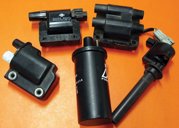
During the past century, ignition coil configurations have evolved from oil-filled canister to epoxy-filled to e-core to waste spark and to the most modern coil-on-plug or “pencil” coils. Whatever the configuration, an ignition coil creates a spark by transforming amperage into volts.
To illustrate, an oil-filled ignition coil might require about 4 amperes of current at 12 volts to produce 20-30 kilovolts (kV), while a modern e-core or coil-on-plug configuration might require about 7 amperes of current at 12 volts to produce 30-60 kV of high-intensity spark. Keep in mind that, because many different factors affect the voltage multiplication process, the ultimate voltage output will vary according to design and operating conditions.
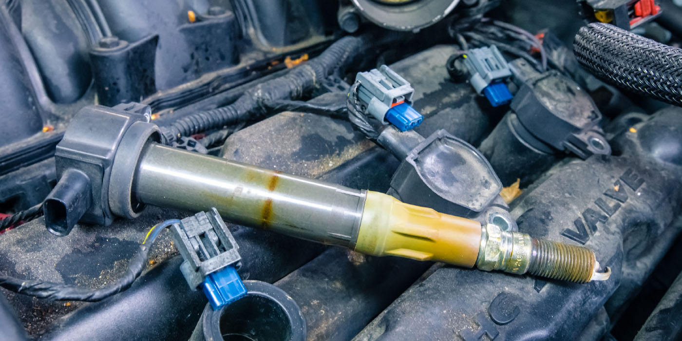
See Photo 1.
Whatever the configuration, an ignition coil has three parts: a primary circuit, a secondary circuit and a soft-iron core. A magnetic field is created around the soft-iron core when an electric current flows through the primary circuit or winding. When the current flowing through a few hundreds of turns of primary winding is interrupted, the resulting magnetic field collapses into many thousands of turns in the secondary winding. By “cutting” the magnetic field many thousands of times, the secondary winding multiplies or transforms low battery voltage into the voltages needed to create an ignition spark.
Keep in mind that the actual output voltage of the coil depends upon the air/fuel (A/F) ratio and the running compression of the engine at the spark plug gap. In general, lean A/F ratios and high cylinder pressures tend to increase the voltage requirement at the spark plug.
Primary Circuit
An ignition coil primary circuit includes the battery voltage or B+ terminal attached to a 12-volt current source and a ground or B- terminal attached to a power transistor that controls primary current flow. To create a spark, the power transistor is commanded by the Powertrain Control Module (PCM) to form a magnetic field in the coil by grounding the primary circuit. Coil “saturation” occurs as the magnetic field is formed. The PCM then commands the power transistor to interrupt the primary circuit and collapse the magnetic field, which then creates an ignition spark.
The primary circuit on-time is generally referred to as “dwell angle” on distributor ignitions and “duty cycle” on distributorless ignitions. Dwell angle and duty cycle begin when the primary circuit is grounded and ends when the primary circuit is interrupted.
While some import electronic ignitions mount a power transistor directly onto the coil, the power transistor in most ignitions is incorporated into a separate ignition control module (ICM). To further simplify ignition hardware, most modern configurations incorporate the power transistor or primary ignition “driver” into the PCM.
Because most modern ignition systems are capable of producing secondary voltages up to 60,000 volts or 60 kV, the ignition systems are programmed to reduce coil operating temperatures by reducing the duty cycle or “on-time” at idle speeds, and also by increasing the duty cycle at high engine speeds. This feature increases coil life by reducing the coil’s internal operating temperature.
Secondary Circuit
The secondary circuit of a distributor ignition system is comprised of the secondary ignition coil windings, distributor cap, distributor rotor, spark plug cable and spark plug. Distributorless systems have eliminated the distributor cap and rotor, but have retained the spark plug cable.
Toyota, among others, often utilizes a “hybrid” waste-spark ignition on V-block engines. In this configuration, the ignition coils on one cylinder bank are mounted directly onto the spark plugs, and the spark plugs on the opposing bank are connected to the coils by ignition cables. In contrast, a dedicated COP ignition system mounts the coil directly onto the spark plug. Obviously, the COP system has the least number of components to fail.