If serial data buses did not exist, a wiring harness would have to be five times its normal size and use twice as many sensors to deliver the same level of functionality and safety we see in the modern vehicle. For example, take a brake pedal sensor. On a modern vehicle, the position of the brake pedal is used by the shift interlock, ABS system, cruise control, traction control, brake lights and electric emergency brake. If each system required its own switch and wiring, the complexity of the wiring harness and switches would be a diagnostic nightmare.
Serial data buses help to eliminate multiple sensors and wiring. One sensor can share information with multiple modules without having to connect directly to the multiple modules.
Serial data buses may seem like a daunting concept to some technicians, but understanding them is now a required skill to work on most modern vehicles.
What Is On The Serial Data Bus?
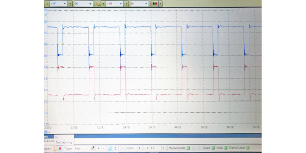
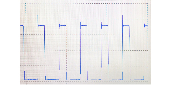
A serial data bus uses voltage to communicate. Modules toggle the signal off and on, making the 1s and 0s of digital binary language function like Morse code. This code can communicate commands that allow something as simple as rolling up a window or as complex as stability control correction.
Zero volts on any serial data bus is translated into binary language as “1,” and when the voltage increases the voltage to a specified level, it equals “0.” Most electronic devices operate on signals toggling between 0 and 5 volts. This includes laptops, DVD players and PCMs.
On most automotive serial data buses, the peak voltage level might be 7 volts. This extra voltage is to accommodate resistance in the wires and ground problems that may cause voltage drops. The extra two volts gives the network a safety buffer that may help the vehicle as it ages.
If a signal was on an equal length of time as it was off, you would have 0, 1, 0, 1, 0, 1 as the binary message being sent out. It could represent what the throttle position voltage is, a signal being sent from the airbag module to the BCM reporting the status of a sensor.
Serial Data Bus Practical Diagnostics
You are never going to be able to look at the signals on a scope, decipher a series of 1s and 0s, and say that it is a command to turn on the brake light. What it can tell you is that a module is communicating and the bus is active.
But, the most critical skill for working on serial data buses is learning how to read the wiring diagrams to figure out how modules and sensors are structured on the bus.
Reading The Wiring Diagram
As a technician in the modern vehicle era, you’re going to need to understand these “bus lines.” The dotted line at the edge of the component, node or module indicates where the CAN bus enters and exits.
Some schematics may include other information in the boxes with two arrows pointing in opposite directions. All two-wire CAN bus lines terminate in a resistor(s) of a known value. This is what produces the correct amount of voltage drop.
Shorts In A Loop
The problem with a loop during diagnostics is if a short circuit occurs. The loop configuration can be easy to diagnose because even with two open circuits, nodes are isolated off the bus. But in a short circuit, with the modules in parallel, the whole circuit goes down.
When a bus shorts, it can be a difficult process to isolate the offending module or section of wiring. In a case where a module shorts out the bus, you would have to unplug them one at a time to see which module eliminates the short circuit. That would not be a good scenario in the repair world because it would take a lot of time to gain access to those modules.
Shorts are one disadvantage of the loop configuration. The advantage is you have a redundancy of wires. Therefore, these are more impervious to an open circuit issue.
Star Bus Configuration
The star configuration’s topology uses a comb, butt connector or shorting bar. It plugs into a female connector.
All of the modules have a single wire coming out of them on the serial data bus leading to that one common connector that would tie them all together in parallel.
The star configuration got its name from the computer industry. For example, an Ethernet connection is a star configuration with computers, printers and servers all connected to an Ethernet hub.
Star connectors are often located near the DLC, but note that there are exceptions. And, some manufacturers solder them in place while others don’t, allowing for the connector to be removed a lot easier. On some vehicles, the star connector can be removed and a meter can be connected to each circuit to test for shorts to power or shorts to ground.
If the short is still present with the splice packs removed, it could be the nodes in the loop configuration. In this case, the ABS and instrument cluster modules might be a source of the short to ground or power, and are connected to the splice pack.
Knowing how both shorts to opens and normal shorts (power and ground) behave on a loop or star can help you formulate a more effective plan of action so you can do more in less time.
Article courtesy Underhood Service magazine.