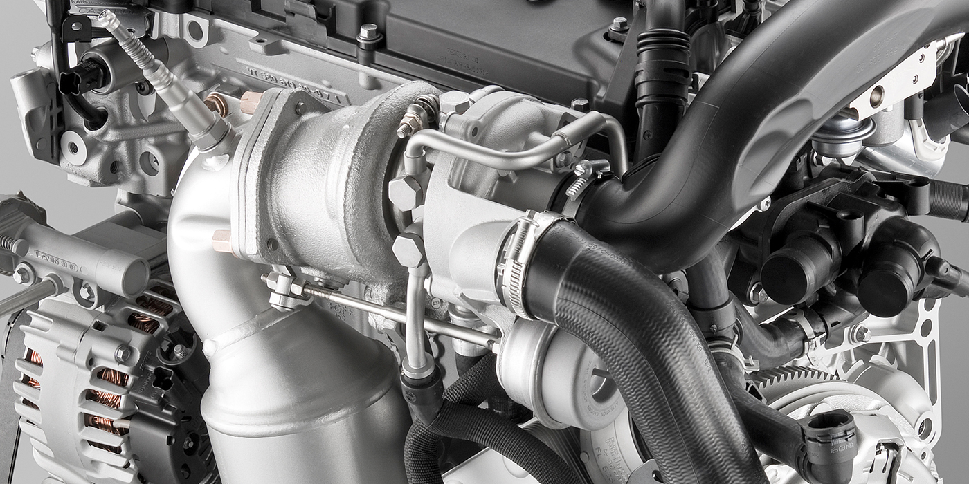
An oxygen sensor (O2) is a vital part of the fuel and emission-control system. It measures the difference in oxygen in the air on the outside of and inside the exhaust. It reports its finding to the ECU to calculate the exact amount of fuel the injector should pulse into the cylinder to create combustion. The main function is to maintain efficient combustion without being too lean or too rich.
In a closed-loop system, the O2 sensor monitors the air/fuel ratio 100 times per second to make minor fuel-trim corrections. Fuel can be added or reduced to ensure this ratio is the stoichiometric ideal, helping the engine burn fuel more efficiently.
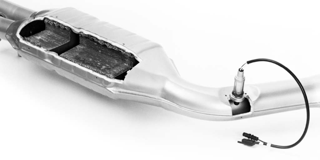
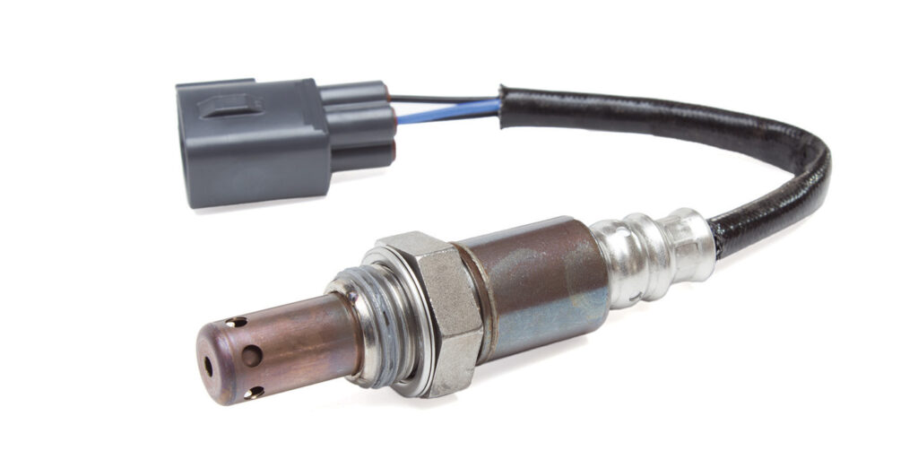
The core of most narrowband O2 sensors is made of zirconia, which helps produce a voltage according to the amount of oxygen in the exhaust. The sensor element is a ceramic cylinder that is plated inside and outside with porous platinum electrodes. It measures the difference in oxygen between the exhaust gas and the external air and then produces a voltage or changes its resistance depending on the difference between the two measurements.
Oxygen sensors work best when they’re heated to approximately 600 F. Most newer O2 sensors come with a heating element encased in ceramic that quickly brings the tip up to temperature. Older sensors, without heating elements, will eventually be heated by the exhaust. Still, there’s a lag time between when the engine is started and when the sensor gets to optimum temperature. The time it takes for the exhaust gases to bring the probe to temperature depends on the ambient air temperature and the layout of the exhaust system. It can take several minutes without a heater circuit.about:blank
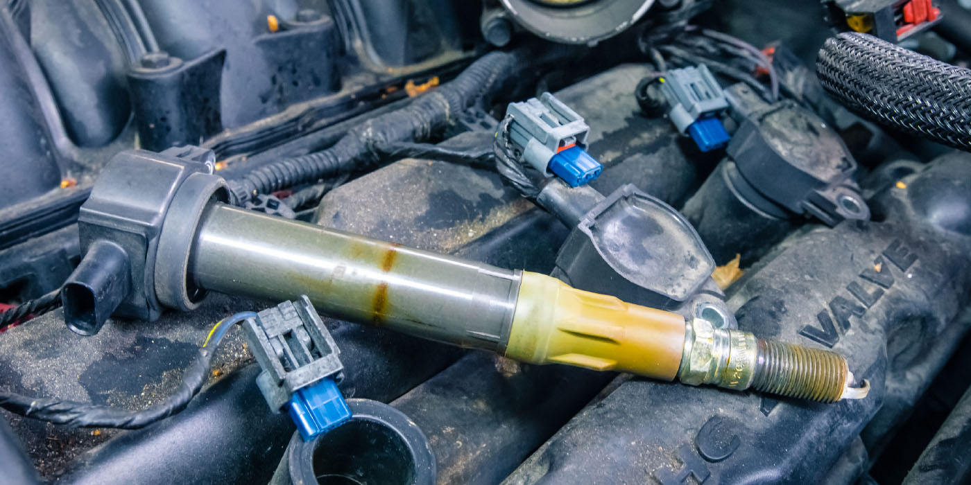
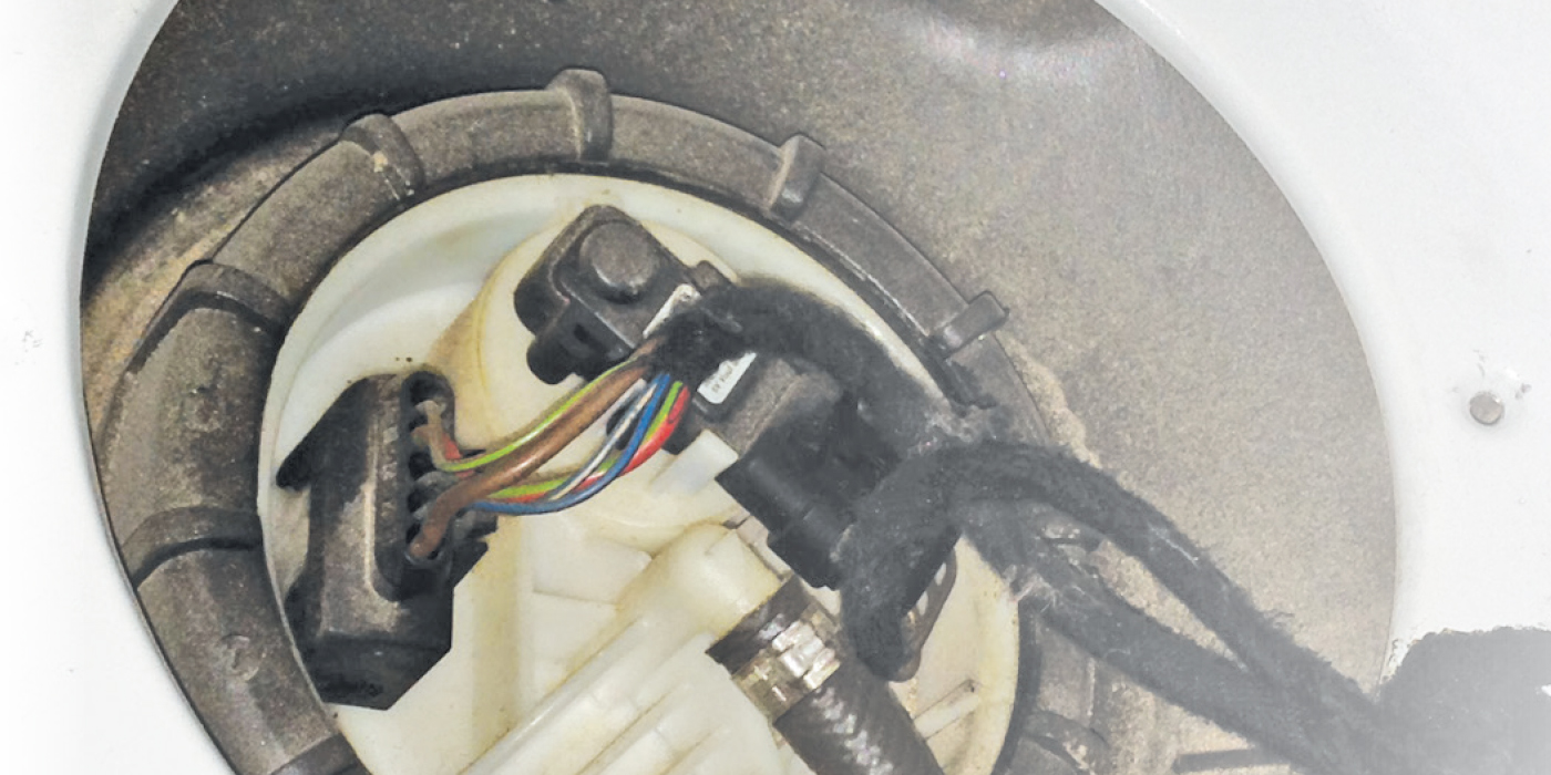
Today, most O2 sensors have four wires: two for the lambda output and two for the heater circuit. However, some use the metal case to ground the sensor element signal, so they only use three wires. Earlier non-electrically heated sensors had one or two wires.
The lifecycle of a typical heated O2 sensor is about 100,000 miles in normal conditions. Single-wire non-heated sensors tend to fail due to the buildup of soot on the ceramic element, which lengthens its response time and may altogether quit reading oxygen. With heated sensors, deposits are burned off during operation, and failure usually results from a bad heater circuit or clogged converter. This will cause a lean mixture, where the ECU enriches the fuel in the mix. Too much fuel loads the exhaust with carbon monoxide and hydrocarbons, and fuel economy decreases.
Another common cause of the premature failure of O2 sensors is when they become contaminated with grease or silicates, which are commonly used as corrosion inhibitors in some antifreeze types. The deposits on the sensor may appear shiny white and grainy light gray. Oil leaks also can contaminate the probe tip with an oily black residue and lead to slow or no response.about:blank
An overly rich mixture causes a buildup of black powdered deposits on the probe. This may be caused by the probe failing or by a problem elsewhere in the fuel system. You can test an O2 sensor with a probe by attaching one lead to the signal wire and the other to the ground to check for voltage. These sensors read an increase in oxygen as a lean condition and should produce close to 200 millivolts (0.20 volts). The sensor is bad if it doesn’t respond or is slow to respond. The issue could be a vacuum leak or some other component. You also can check the heater circuit for resistance with an ohmmeter. If there’s no resistance, the circuit is bad, and the sensor must be replaced.
This article is courtesy of Counterman.