Full-size four-wheel-drive pickup trucks already represent a significant portion of chassis and driveline sales. Built for towing and hauling, but often used for off-road adventure, these trucks are popular with both tradesmen and weekend warriors alike. While all current mid-size and half-ton 4×4’s have evolved toward a CV halfshaft front axle design, the monobeam (solid-axle) designs that dominated the truck market throughout the 1970s and 80s still survive in many modern 3/4 and 1-ton platforms. The most popular of these are the Dana 60 and the American Axle & Manufacturing 925. In many older platforms, the Dana 44 and 50 series as well as 8.5-inch GM Corporate 10-bolt solid axles share many of the same design features, and require similar service procedures.
Servicing the ball joints and U-joints on monobeam axles requires a fair amount of steering knuckle disassembly just to access these components. Wear and tear on the components associated with these knuckle and hub assemblies, as well as the service procedures themselves, often necessitates the replacement of various bearings and seals in the axle and knuckle assembly. Identifying and properly cataloging these components can be a frustrating task for many parts specialists, due to confusing or vague catalog descriptions. Let’s take a look at the bearings and seals that are most likely to be replaced in these axles.
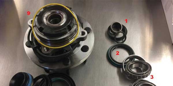
Older Dana and GM Corporate front axles were designed much like the full-floating axles found on the rear of these trucks. Their hollow spindle design allows for the axle shaft to pass through the knuckle and connect to the rotating hub, without supporting any of the weight of the chassis. Each hub (or hub and rotor assembly) rides on a pair of tapered roller bearings (3), accompanied by an inner grease seal (2). While the majority of these hub designs use two different size inner and outer bearing sets, some applications use the same bearing and race numbers in both positions, for a total of four sets per axle.
Bearing preload is adjusted by tightening a pair of specially-designed spindle nuts (4) located behind the manual locking hubs. To support the axle stub shaft as it passes through the spindle, a Torrington-style needle bearing is pressed into the inner bore of the spindle, sealed with a pair of soft rubber seals, as well as a thrust washer and metal dust shield (also known as a “slinger”).
This bearing is widely referred to as a “spindle bearing,” and is sold individually, as well as in a “spindle bearing kit,” (1), which includes the bearing as well as the seals, washer and slinger as required. Worn U-joints can accelerate wear on the spindle bearing, and this kit can be a great add-on sale, saving the customer future headaches. Specially designed locknut sockets, as well as a spindle pulling adapter and slide hammer are also recommended for servicing these bearings.
Of course, the integrated hub assembly has largely replaced serviceable tapered roller bearings in modern 4×4 applications. These sealed units offer longer service life, without the periodic repacking and adjustment common to older designs. However, when servicing these steering knuckles, there are still opportunities for additional bearing and seal sales. One commonly-requested “knuckle busting” monobeam application is the 1999-and-newer Ford Super Duty platform.
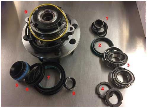
In addition to the hub assembly, there are usually three seals, an O-ring and a needle bearing cataloged for the F250 and F350. Removing the hub and disassembling the knuckle often leads to replacement of many of these pieces, due to the design of the seals. These trucks have vacuum-actuated hub locks, so a tight seal is important to the proper operation of the system.
Whenever the hub assembly is removed from the knuckle, the O-ring (9) should be replaced to ensure a good vacuum seal. This O-ring is usually included with the new hub assembly, but is available separately as well. When it comes to cataloging, the three “axle” seals seem to give technicians as well as parts specialists the most trouble. The largest diameter seal (7) is often cataloged as an “outer axle seal,” although most techs seem to call it a “hub seal” or an “inner seal,” because of its location on the inboard side of the knuckle.
This seal is prone to damage during U-joint replacement, and replacement requires a specialized driver to seat it properly on the axle stub shaft. When cataloging this seal, it can easily be confused with the “inner axle seal” (5), which fits deep inside the axle tube, near the differential side bearings. This particular seal, because of its location and the difficulty in replacing it, is rarely replaced during knuckle or axle shaft service, unless it is leaking.
The last of our three seals is cataloged as the “axle spindle seal” (6) despite its location at the end of the axle tube. This seal is more of a dust seal than an oil seal (the axle tube does not contain lubricant), and slip-fits over a journal on the inboard side of the U-joint yoke.
The one bearing common to both of these knuckle designs is the spindle bearing (8). Instead of being pressed into a hollow spindle, this bearing is inserted into the back of the hub assembly to help support the axle stub shaft. This bearing comes preinstalled in aftermarket hubs, but like the vacuum O-ring, is also available separately when the technician chooses to reinstall an existing hub assembly.
Article courtesy Counterman.