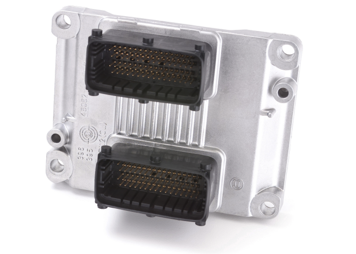
So… You plug in your diagnostic scanner or code reader, only to find out that you cannot communicate with the PCM. Bad PCM Right? Not necessarily!
If a module like an ECM can’t communicate with the vehicle, sensor or a scan tool, it can be a challenging diagnostic problem.
One of the easiest tests to perform is to see if there is power and ground being supplied to the ECM. This can be performed by using the OBDII connector. Pin 16 is the positive voltage side being supplied to the ECM. Pin 4 is chassis ground and is a ground taken from the body of the vehicle. Pin 5 is the signal ground. What is the difference between the grounds? On some vehicles, the wires for pins 4 and 5 attach at the same point of the body. Some vehicles use a “clean” ground for pin 5 that could come from the ECM, power distribution module or a ground that is not shared with components like radios or ignition systems.
Most ECMs are not “plug and play” parts. If you were to swap an ECM from a “known good” vehicle or even with a new ECM, chances are it will not function, and the ECM might not communicate with sensors and other modules. This is because the software that is unique to the vehicle is not programmed or flashed into the module’s memory when it comes from your parts supplier.
If the programming is present or you are trying to program the module, and it still will not communicate with your scan tool or laptop, the issue could be with the OBDII connector under the dash. Often, the connector can be damaged if the scan tool or code reader has been pushed in and out frequently. Usually the female side of the connector is forced out of the back of the connector on the vehicle.
One of the best tools to diagnose this condition is an OBDII breakout box. Since most networks on the vehicle can be accessed through the OBDII connector, this tool helps you observe if the network is active, open or shorted.
With any communication network, the resistance in the circuit, resulting voltage and circuit condition can determine if information is being communicated with other modules. If there is high resistance in a module or part of the wiring harness it can bring down the network. The same is true for an open or short to ground.
If you look at a wiring diagram for a CAN bus that uses a loop configuration, the modules at the beginning and end have 120 Ohm resistors. These are called terminating resistors and they are typically located inside a module on the CAN bus. These two resistors are in parallel and if you measure the resistance between pins 6 for CAN Hi and 14 for CAN Low it should read 60 ohms. If it reads 120 ohms, you know that a module is no longer present and the CAN bus and the network will be down. Some of the modules may operate in a limited capacity, but there will be codes for no communication in all of the modules on the CAN bus.
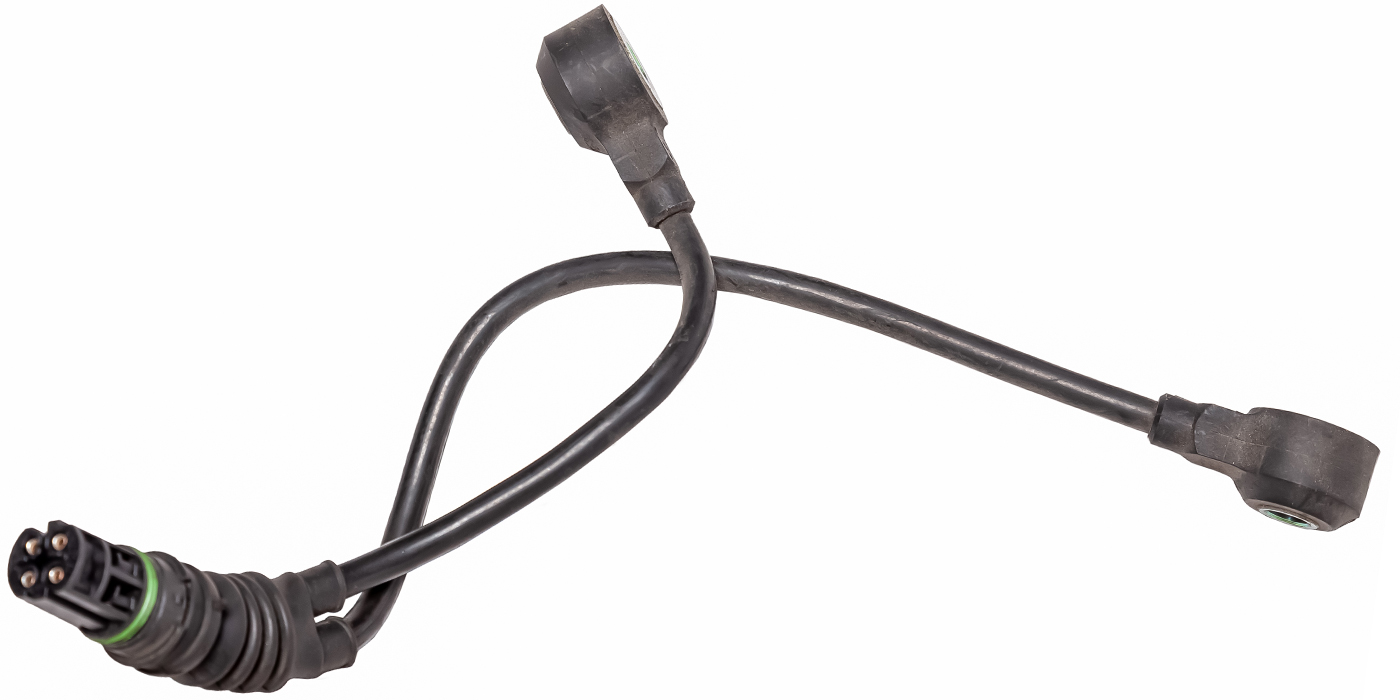
The other type of communication issue could be with a sensor or actuator. With these types of errors, you can communicate with a module, but the information from a sensor is missing or implausible. Also, an injector may not pulse, or an ignition coil might not fire. Sometimes, there will be a DTC for the circuit; sometimes there won’t be a code. So, again, the communication issue could be with the sensor or actuator, or the problem could be on the module’s circuit board.
Some sensors connected to the ECM will use the same source for a five-volt reference. In some ECUs, the crankshaft position, camshaft position and maybe the MAP sensor will use the same five-volt source. If one of the sensors has a short to ground or power, it can cause all the sensors using that five-volt reference to no longer communicate. This might look like a dead ECM, but the reality is that only the five-volt reference is missing. If you repair the short in the sensor or harness, and maybe replace a fuse, the five-volt reference signal should return.
Circuits on the ECM circuit board can be classified into four categories
First, you have the circuits and components that process and compute. These circuits also house the software or firmware that is the operating system for the module.
Second, communication circuits allow the module to communicate on the networks of the vehicle with other modules. This can include CAN, ISO, KWP and others.
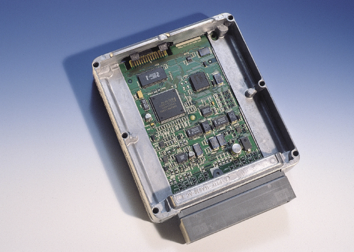
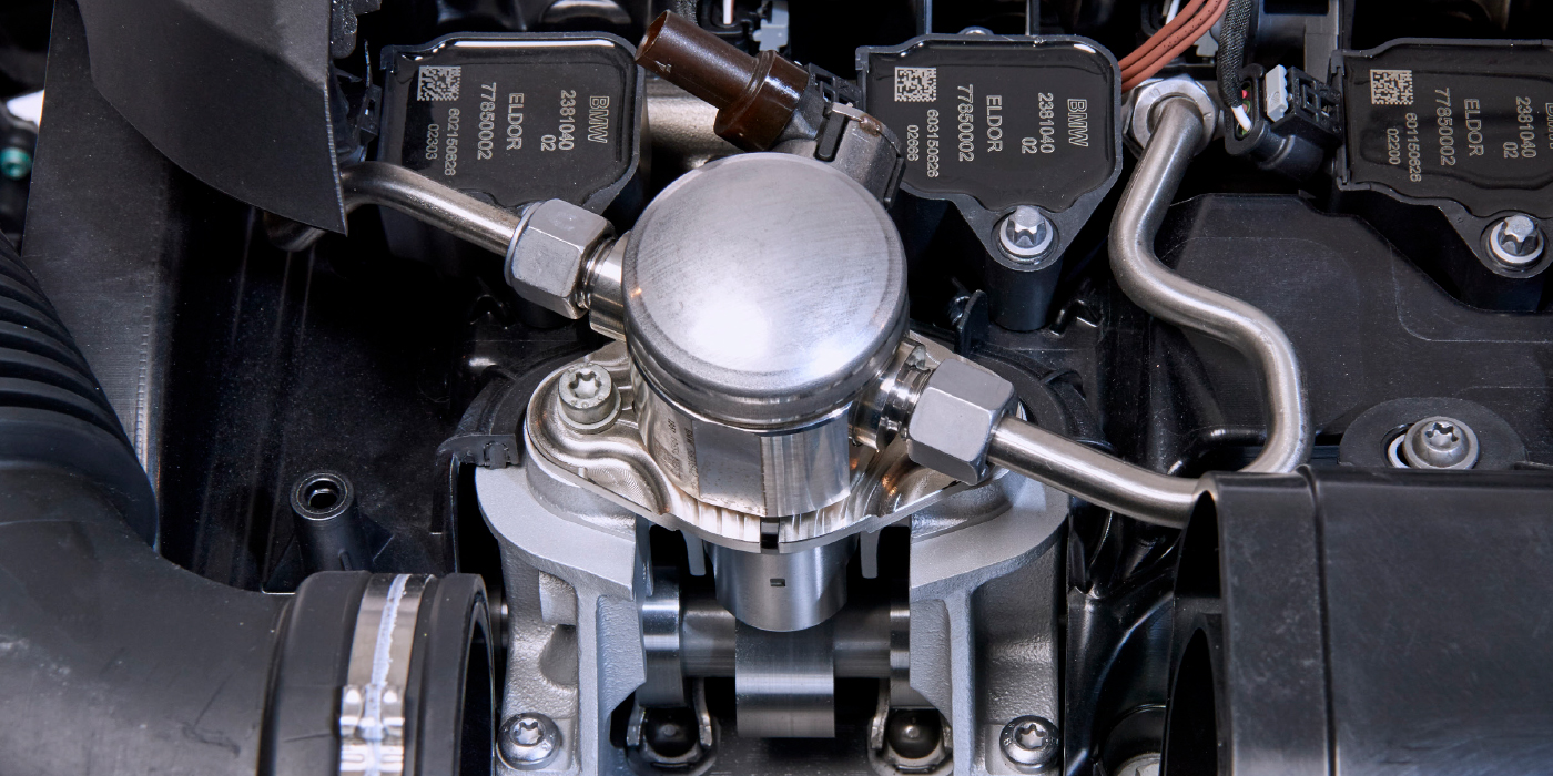
Third, you have circuits that receive information from sensors and generate reference voltages. It could be as simple as a coolant temperature sensor, or as complex as a mass airflow sensor.
Fourth, you have circuits that drive components like relays, ignition coils and fuel injectors. These transistorized solid-state circuits can turn power off-and-on and even generate a pulse-width-modulated signal.
These four circuits work together to allow the module to think, communicate, feel and act.
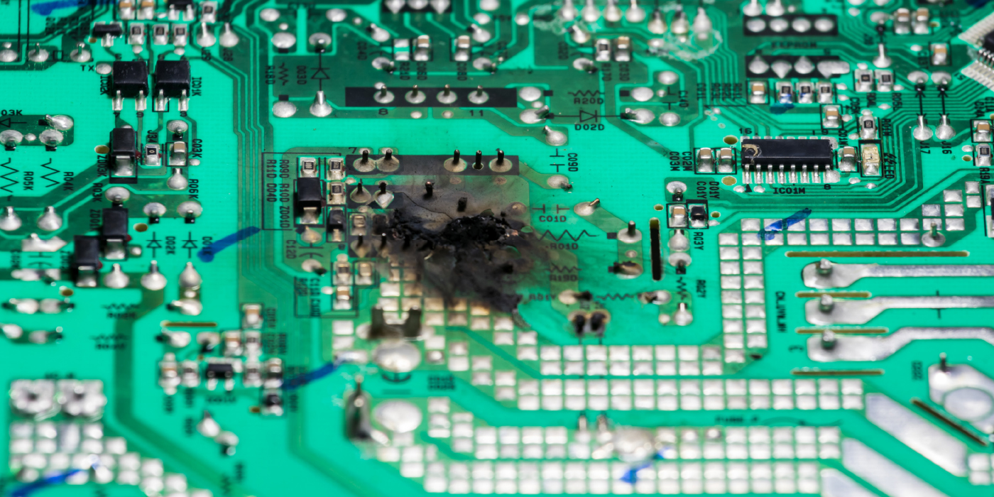
All of these circuits inside the module can be damaged by heat and vibration. Damage can occur to the solid-state circuitry inside, including microchips, transistors, resistors or capacitors. The solder that connects the components to the circuit board can also fail.
But, a lot of the damage to an ECM comes from the connected components. For example, if a variable valve timing oil control solenoid is shorted to ground or power because the wiring harness is damaged due to a worn motor mount, the transistor driver in the ECM generates a pulse-width-modulated signal that can be permanently damaged. There is no way to repair the driver on the circuit board. Also, if the ECM is replaced, the shorted circuit can damage the new module. Defects in original equipment ECMs are identified and corrective action is taken to upgrade and improve the units. Certain engine control computer upgrades, for example, include upgraded components installed in critical circuits, installation of heavier injector transistors, circuit protected quad drivers, reflow of solder joints, and an upgraded power supply diode for the ignition circuit to improve durability.